Table of Contents
Advertisement
Quick Links
Advertisement
Table of Contents
Troubleshooting

Subscribe to Our Youtube Channel
Related Manuals for Diamond DST/2-15 AG


Summary of Contents for Diamond DST/2-15 AG
- Page 1 MOD : DST/2-15AG(230/3) Production code : SOFTGEL 320 AIR (230/3) /202...
- Page 2 Operating and maintenance manual Operating and maintenance manual DST/2-15 AG - DST/2-15 AG - DST/2-27 AG DST/2-27 AG Translation of the original instructions...
- Page 4 All of the staff at DIAMOND and its dealers hope that you will enjoy working with our machines! This operating and maintenance manual is part of the machine and must always be kept with it, even...
-
Page 5: Table Of Contents
CONTENTS 1 GENERAL INFORMATION 1.1 General safety instructions 1.2 Information about precautions, specific warnings and symbols 1.3 Testing, guarantee and liability 1.4 Purpose of the manual • 1.4.1 Structure of the manual • 1.4.2 Modifications and additions 1.5 Manufacturer identification •... - Page 6 Introduction Contents 5 MACHINE OPERATION 5.1 Controls 5.2 Switching on and starting the machine • 5.2.1 Filling of the cylinder for each mix reserve tank 5.3 Programming • 5.3.1 Adjusting the CONSISTENCY of the ice cream (P1) • 5.3.2 Adjusting the PRESERVATION of the ice cream (P2) •...
-
Page 8: General Information
Chapter 1 General Information 1 GENERAL INFORMATION 1.1 General safety instructions Before using the machine, carefully read all of this manual, which is an integral part of the machine. Knowing the information and instructions in this manual is essential for users to use the machine correctly and safely. The manufacturer declines all responsibility in the event of modifications, tampering or any operations that may put the health and safety of people and/or objects at risk, carried out in a way that does not coincide with what is specified in this manual. -
Page 9: Testing, Guarantee And Liability
1.3 Testing, guarantee and liability Testing Before being sent to the customer, the machine must successfully pass testing by the manufacturer. Guarantee The manufacturer guarantees the machines put on the market for 12 months from the date of delivery. During the guaran- tee period the seller undertakes to substitute, free of charge ex works, any parts which may develop a fault due to obvious manufacturing defects or poor quality materials. -
Page 10: Modifications And Additions
EUROPE S.A. to apply such changes to a machine previously supplied, nor to consider it and the related manual lacking and inadequate. DIAMOND EUROPE S.A. reserves the right, should it deem it appropriate and for valid reasons, to update the manuals already on the market, sending its customers sheets of technical and/or operating updates which must be considered and kept in the manual. -
Page 11: Ordering Spare Parts
1.5.2 Ordering spare parts When requesting spare parts, contact your dealer or consult the up-to-date list of authorised service centres on the official DIAMOND EUROPE S.A. website: https://www.diamond-eu.com/. 1.6 Machine identification data - CE marking The data plate with CE marking is located at the top of the machine rear panel and shows all of the data needed for machine identification. -
Page 12: Intended Uses
Chapter 1 General Information 1.7 Intended uses The DST/2 range of machines are designed to: 1. stir and freeze in one or two of the internal machine cylinders the mixture picked up from one or two of the tubs that are filled so their contents can be turned into soft ice-cream or frozen yogurt. -
Page 13: Packaging, Transportation And Storage
1.9 Packaging, transportation and storage The machine is packaged in a wooden or cardboard crate on a pallet having dimensions and features suitable for the type and weight of the machine. The machine will be delivered packaged, ensuring that it is protected from the elements. Each package is marked with the following information: •... -
Page 14: Technical Specifications
The DST/2 range of machines covered by this manual, are machines for making soft ice cream and frozen yogurt. The range consists of the following models: - DST/2-15 AG (counter model) fitted with 2 horizontal production cylinders - DST/2-27 AG (floor-standing model) fitted with 2 horizontal production cylinders The machines are designed and built to use gravity to transfer the mix/product from the reserve tank to the cylinder. -
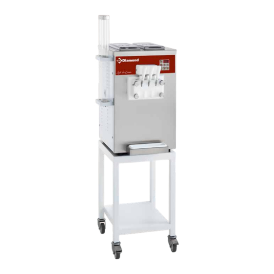
Page 15: Illustration Of The Machine As A Whole And Its Components
2.2 Illustration of the machine as a whole and its components Cone tube cover Cone tube Cone retaining valve Mixer Cylinder Filling tube Mix reserve tank Tank cover Control panel Dispensing lever Dispensing tap Dispensing tap fixing knob Drip tray Air condenser grille Rear wheels (for floor-standing models) Front wheels fitted with brakes (for floor-standing models) - Page 16 Chapter 2 Technical Specifications...
-
Page 17: Working And Control Position
2.3 Working and control position The operator must stand in front of the machine and load the ingredients, programme the recipe, start the processing and unload the processed product at the end of the recipe. 2.4 Machine technical data Model DST/2-15AG DST/2-27AG Net weight... -
Page 18: Noise
Chapter 2 Technical Specifications Model DST/2-15AG DST/2-27AG Dimensions L (mm) D (mm) H (mm) 1450 D2 (mm) E (mm) RATED POWER / RATED CURRENT Power supply voltage (Volts) Frequency (Hz) Phases DST/2-15AG DST/2-27AG 2.4 kW - 13 Amp. 2.4 kW - 14 Amp. 2.4 kW - 10 Amp. -
Page 19: Items Supplied With The Machine
2.6 Items supplied with the machine The machine is supplied together with the following items: Operating and maintenance manual. Kit of gaskets and packet of food-safe lubricating grease 2 bottle brushes (small/large) for cleaning. 2 cone tubes. Upper cone support bracket. Lower cone support bracket. - Page 20 Chapter 3 Safety regulations 17. Do not use the machine with damp or wet hands. 18. Always wear suitable gloves and a hair cover for hygiene. 19. Pay maximum attention to all caution and danger signs on the machine. 20. The machine must be installed in a location protected from rain and sun. 21.
-
Page 21: Safety Symbols And Stickers
3.2 Safety symbols and stickers On the machine there are symbols/stickers for highlighting: what you must not do, important information and warnings: This symbol indicates the presence of an electric shock hazard. It indicates to the relevant personnel that they risk an electric shock if they do not work in compliance with safety regulations. -
Page 22: Installation Instructions
Chapter 4 Installation 4 INSTALLATION INSTRUCTIONS 4.1 General requirements INSTALLATION MUST ONLY BE PERFORMED BY QUALIFIED TECHNICAL PERSONNEL. Once the package is near to the machine installation location, cut the straps (A) and remove the cardboard (B) by pushing it upwards. -
Page 23: Spaces Needed For Use Of The Machine
4.3 Spaces needed for use of the machine The machine must be positioned on a solid, level and even floor. It must not be directly exposed to sunlight or near to heat sources. Keep the machine air inlets clear to allow adequate air cir- culation around it. -
Page 24: Electricity Supply
Chapter 4 Installation B Tap dispensing levers • Remove the fixing pin (7) from the tap horizon- tally. • Position the levers (8) in such a way that the relative forks (9) engage with the pin (10) of the relative pistons (11). •... -
Page 25: Air-Cooled Machine
THE USE OF EXTENSION LEADS WHICH HAVE A CROSS-SECTION DIFFERENT TO THAT OF THE MACHINE POWER CABLE MAY RESULT IN THE FOLLOWING FAULTS: 1. SLOW MOTOR START WITH TRIPPING OF OVERLOAD SWITCHES 2. MOTOR OVERHEATING WITH A DROP IN POWER 3. -
Page 26: Water-Cooled Machine
Chapter 4 Installation 4.7 Water-cooled machine For machines with a water-cooled condenser, a water supply tube and a water drainage tube have to be fitted. Connect a valve or tap (1) before the delivery tube. The threaded connectors are on the back of the machine, in the lower area. Each connector is marked with a label indicating its purpose, as below: IN - Machine water infeed (pressure between 1 and 7 bar) OUT - Machine water outfeed... -
Page 27: Machine Operation
5 MACHINE OPERATION 5.1 Controls The control panel functions are illustrated below: ON/OFF button For switching the machine on and off. Press to prepare the machine to operate and subsequently the temperature of the reserve tank(s) is shown on the digital display (2). - Page 28 Chapter 5 Using the machine 7. Production Button Use this button to start ice cream production. When production is ON the warning light (7a) in the button is lit. Press the button to start ice cream production in the cylinder(s) and keep it in a condition that ensures optimum consistency for dispensing. When this button is pressed the mixer(s) in the cylinder(s) and the machine cooling system are switched on automatically.
-
Page 29: Switching On And Starting The Machine
5.2 Switching on and starting the machine Connect the machine power cable to a socket and check that the power LED (1) is lit. Press the ON/OFF 0/1 button to prepare the machine to operate and subsequently the temperature of the mix reserve tanks is displayed on the digital display (2). -
Page 30: Filling Of The Cylinder For Each Mix Reserve Tank
Chapter 5 Using the machine 5.2.1 Filling of the cylinder for each mix reserve tank - Remove the lid of the mix reserve tank and remove the feeding tube. - Pour ½ liter of mix into the reserve tank. - Wait until the mix flows into the cylinder. 1/2 L - Reassemble the feeding tube and pour the remai- ning mix into the reserve tank. -
Page 31: Programming
5.3 Programming DURING TESTING, THE MACHINE WAS PROGRAMMED WITH OPTIMAL PARAMETER SETTING VALUES FOR THE OPERATING CYCLE. DO NOT CHANGE PROGRAMMING UNLESS THIS IS STRICTLY NECESSARY. IF PARAMETER VALUES DO NEED TO BE ALTERED, MAKE ANY NECESSARY MACHINE PROGRAM- MING CHANGES BEFORE STARTING PRODUCTION. ▪... -
Page 32: Adjusting The Consistency Of The Ice Cream (P1)
Chapter 5 Using the machine 5.3.1 Adjusting the CONSISTENCY of the ice cream (P1) ▪ Having pressed the “Programming/Reset” button (A), the P1 code flashes on the digital display. Press the button again. A number value indicating the ice cream consistency set appears on the dis- play. -
Page 33: Adjusting The Temperature Of The Mix Reserve Tanks (P3)
5.3.3 Adjusting the TEMPERATURE of the mix reserve tanks (P3) ▪ Press the “Programming/Reset” button (A) again and the P3 code will flash on the digital display. This code indicates the possibility of changing the temperature of the mix reserve tank(s). Press ad- justment buttons (B) and (C) to increase or reduce the temperature of the mix reserve tank(s). -
Page 34: Production
Chapter 5 Using the machine 5.4 Production BEFORE STARTING PRODUCTION, THOROUGHLY WASH AND SANITISE THE MACHINE, AS INDI- CATED IN SEC. 6 (WASHING). ▪ Check that the Power On LED (1) is lit and press the machine ON/ OFF 0/1 button. NOTE: For machines fitted with two cylinders to operate correctly, both cylinders must contain the product to be processed. - Page 35 - Place the cone or cup under the tap with the dispensing lever, lower the lever to dispense the ice cream, then return it to the closed position. The central lever allows a mixture of the two ice creams in the cylinders to be dispensed. Productivity, in terms of the ice cream that can be dispensed by the machines and the drawing time, are indicated in the table below (with reference to use of the central lever):...
-
Page 36: Preservation
Chapter 6 Washing 5.5 Preservation THE MIX CAN BE PRESERVED IN THE MACHINE FOR THE TIME CONSIDERED NECESSARY, BUT NOT BEYOND THE EXPIRY DATE OF THE INGREDIENTS/PRODUCTS USED. IF THE PRODUCT IS KEPT BEYOND ITS EXPIRY DATE, YOU MUST DISASSEMBLE, THOROUGH- LY WASH AND SANITISE THE MACHINE PARTS THAT HAVE BEEN IN CONTACT WITH THE PRODUCT, AS EXPLAINED IN SECTION 6 (WASHING), IN ORDER TO PREVENT ANY POSSIBLE PROLIFERATION OF BACTERIA. -
Page 37: Washing
6 WASHING 6.1 Washing and sanitising DO NOT USE WATER JETS, AS THEY MAY DAMAGE THE MACHINE. Sanitising includes all of those activities intended to make hygienic the inner surface of the cylinders and reserve tanks and the removable components that come into contact with the food. Aims of sanitising: To remove all traces of product residues. - Page 38 Chapter 6 Washing 1. Rinse phase: Note: At the end of operations, thorough rinsing is needed, to completely remove product residues from the machine. Proceed as follows: – Depending on the function active, press the “PRO- DUCTION” button or the “PRESERVATION” button to switch it off and interrupt machine operation.
- Page 39 2. Washing with detergent phase: DO NOT USE SOLVENTS OR CORROSIVE PRODUCTS. Proceed as follows: – Pour a detergent solution, at a temperature NOT HIGHER THAN 30°C, into the reserve tanks until they are ½ full. Use a highly effective, neutral detergent. It should be a profes- sional grade detergent specifically for the food sector.
- Page 40 Chapter 6 Washing To thoroughly wash with detergent all components installed on the machine, remove them and proceed as follows: TURN OFF AND ISOLATE THE MACHINE POWER SUPPLY BEFORE PERFORMING THE FOL- LOWING OPERATIONS. TURN OFF THE MACHINE BY PRESSING THE "0/1" ON/OFF BUTTON AND SET THE MAIN ON/OFF SWITCH TO “0”.
- Page 41 Removing the mixers – Take the mixers (12) out of the cylinders (13) hori- zontally. – Remove the seal (14) from the mixer (12). b) Washing with detergent: Use a highly effective, neutral detergent. It should be a professional grade detergent specifically for the food sector.
- Page 42 Chapter 6 Washing Note: Also thoroughly wash the outer parts of the machine: – Use a disposable cloth (A) to clean the upper surface and the outer panels of the machine. – Use a disposable cloth (A) to clean the covers of the reserve tanks.
- Page 43 3. Re-fitting components: After washing, re-fit all of the machine components as described below: Re-fitting the mixers Note: Regularly check the integrity of the gaskets and substitute them if they are broken, worn or swol- len. Only use original gaskets, made of food-safe rubber. The gaskets and their housings must be carefully lubricated before re-use.
- Page 44 Chapter 6 Washing – Carefully position the mixers (12) in the cylinders (13), rotating them so that the mixer shafts (20) are properly inserted in their housings on the bottom of the cylinders (13). Re-assembling the dispensing tap components Note: Regularly check the integrity of the gaskets and substitute them if they are broken, worn or swol- len.
- Page 45 Re-fitting the dispensing tap on the machine – Position the gaskets (6) in the tap housings (5). – Fit the tap body (5) on the 4 connecting rods and cross-tighten the clamping knobs (11). Reassembling the carburettor. – Position the gaskets (3) in the carburettor (2) hous- ings.
- Page 46 Chapter 6 Washing – Put a suitable container under the dispensing tap. – Press the “MIX” button and gradually lower all of the dispensing levers, in order to drain out the disinfect- ant solution. OPERATING THE MIXER FOR LONGER IS NOT HELPFUL AND IS HARMFUL. THE LACK OF LUBRICATION ,PROVIDED BY THE INGREDIENTS DURING PRODUCTION, COULD CAUSE WEAR ON THE MIXERS AND/OR THE CYLINDERS.
- Page 47 OPERATING THE MIXER FOR LONGER IS NOT HELPFUL AND IS HARMFUL. THE LACK OF LU- BRICATION ,PROVIDED BY THE INGREDIENTS DURING PRODUCTION, COULD CAUSE WEAR ON THE MIXERS AND/OR THE CYLINDERS. – Press the “MIX” button to stop mixing and return the dispensing levers to the closed position.
-
Page 48: Routine Maintenance
Chapter 7 Maintenance 7 ROUTINE MAINTENANCE ONLY PURCHASE AND USE ORIGINAL SPARE PARTS, WHICH ARE GUARANTEED BY THE MANUFACTURER. CONTACT THE DEALER OR THE NEAREST SERVICE CENTRE TO REPLACE FAULTY OR DAMAGED COMPONENTS. 7.1 Type of checks and interval between them Regular checks of the operation of the parts of the machine most subject to stresses and wear can prevent faults and help to maintain maximum productivity levels, guaranteeing lasting constant operation. -
Page 49: Maintenance Sheets
7.4 Maintenance sheets Substituting gaskets CHECKING INTERVAL: 500 hours or quarterly AUTHORISED OPERATOR: 1 Operator TIME NEEDED: 5 minutes TOOL: Non-metallic pointed tool Regularly check the integrity of the gaskets and substitute them if they are broken, worn or swollen. Only use original gaskets, made of food-safe rubber. - Page 50 Chapter 7 Maintenance Piston gaskets: • Remove the worn gaskets from the pistons using a non-metallic pointed tool, taking care not to damage the housing. • Remove any product residue from the housings and posi- tion the new gaskets on the pistons, taking care to fit the oblique gasket only on the central piston.
-
Page 51: Troubleshooting
8 TROUBLESHOOTING Most faults and problems during machine operation are promptly automatically indicated by the machine. ALARMS STOP THE MACHINE, WITH AN EMERGENCY STOP MESSAGE DISPLAYED ON THE CONTROL PANEL. TO RESTART THE MACHINE, YOU MUST ELIMINATE THE CAUSE OF THE EMERGENCY. People involved in troubleshooting: Operator: person trained in the ordinary operation of the machine who performs initial fault-finding and if possible,... -
Page 52: General Alarm Indications Displayed On The Control Panel - Causes And Solutions
Chapter 8 Troubleshooting... - Page 54 Chapter 8 Troubleshooting...
-
Page 55: Troubleshooting - Flowchart
8.2 Troubleshooting – flowchart In abnormal conditions the machine may malfunction, as specified below: MACHINE DOES NOT OPERATE OR OPERATION IS INTERRUPTED THE MAINS MASTER SWITCH IS IN THE ON (1) POSITION, BUT THE POW- ER LED IS NOT LIT. The plug is not inserted in the Insert it correctly. - Page 56 Chapter 8 Troubleshooting MACHINE REPEATEDLY TRIPS THE ELECTRIC CIRCUIT BREAKERS OR BLOWS THE MAINS FUSES. Contact the Technical The capacity of the electrical system is not sufficient to power the assistance service. machine. The electrical specifications of the Contact the Technical overload switches or fuses are not assistance service.
- Page 57 UNUSUAL NOISE The mixer motor and the compres- Contact the Technical sor motor create excessive vibra- assistance service. tions and/or operate abnormally. Contact the technical assistance service COOLING IS INSUFFICIENT OR SWITCHES OFF IN A FAULTY WAY AIR-cooled machine There are obstructions in front of Restore the minimum distance required.
-
Page 58: Inactivity
Chapter 8 Troubleshooting 9 INACTIVITY 9.1 Keeping the machine efficient if it remains inactive If the machine will not be used for a lengthy period, follow these instructions: - Sanitise the machine as described in sec. 6.1. - Switch off the machine using the I/O - ON/OFF button, power down at the mains master switch and take the plug out of the socket. -
Page 59: Decommissioning The Machine
10 DECOMMISSIONING THE MACHINE 10.1 Description of method of disposal The lifetime of the machine estimated by the manufacturer is 20,000 hours (10 years) of operation under normal operating conditions, described in this operating manual. At the end of its lifetime the machine must be disposed of in accordance with the regulations in force in the country where it was used, concerning the disposal of waste electrical and electronic equipment. - Page 60 INFORMATION FOR USERS In accordance with Directives 2011/65/EU and 2012/19/EU and subsequent amendments and additions, on the restriction of the use of certain hazardous substances in electrical and electronic equipment (EEE) and waste electrical and electronic equipment (WEEE), we hereby inform you that: “the crossed bin symbol on the device or on its packaging indicates that, at the end of its life, the product must be disposed of separately from other waste”.
- Page 61 DIAMOND EUROPE S.A. 92 Chaussée de Vilvorde - 1120 Brussels - Belgium Edition 06-2023...
Need help?
Do you have a question about the DST/2-15 AG and is the answer not in the manual?
Questions and answers