Advertisement
Quick Links
Advertisement

Related Manuals for NCR 7358-K704


Summary of Contents for NCR 7358-K704
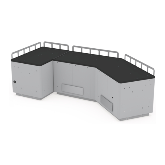
- Page 1 Kit Instructions Large Basket Module (Medium Gray) 7358-K704 Issue B...
- Page 2 NCR, therefore, reserves the right to change specifications without prior notice. All features, functions, and operations described herein may not be marketed by NCR in all parts of the world. In some instances, photographs are of equipment prototypes. Therefore, before using this document, consult with your NCR representative or NCR office for information that is applicable and current.
-
Page 3: Revision Record
Revision Record Issue Date Remarks Mar 2021 First Issue May 2021 • Updated illustration and part numbers in the Kit Contents section. • Updated procedures. • Added procedures for NCR FastLane SelfServ™ Checkout (7370). - Page 4 Large Basket Module (Medium Gray) This publication provides the steps for installing the 7358-K704 Large Basket Module (Medium Gray) to a SelfServ Checkout unit. The kit is designed using modules that are ready to be assembled at the site. The NCR FastLane SelfServ™ Checkout with a Bagging Area (Bagwell) Module or...
-
Page 5: Kit Contents
Large Basket Module (Medium Gray) Kit Contents Part Number Description 497-0530586 Large Basket Kit (WM Medium Gray) 497-0530517 Hole Plug, 1.000", WM Medium Gray (6 pcs) - Page 6 Large Basket Module (Medium Gray) Part Number Description 497-0530518 Hole Plug, 2.000", Wm Medium Gray (5 pcs) 006-8627877 Push In Rivet, 0.25", Black (30 pcs) 006-8627878 Wingnut, 1/4-20, Zinc-Plated Steel (20 pcs) 006-8628097 Plastic Knob, 1/4-20 X 5/8" Steel Stud (8 pcs) 497-0528528 Large Basket, Angled Tie-Bar (2 pcs) 497-0528530...
- Page 7 Large Basket Module (Medium Gray) Part Number Description 795-0286828 Large Basket, Corner Center Panel (WM Medium Gray) (2 pcs) 795-0287828 Large Basket U-Module Assembly (WM Medium Gray) (6 pcs) 497-0457054 Black Nylon Spacer 15Mm Od X 10.4Mm Id X 10Mm L (4 pcs) 497-0530064 Big Basket V-Bagwell Tray Assy 795-0287628...
- Page 8 Large Basket Module (Medium Gray) Shipping Dimension and Weight This section shows the approximate shipping dimension and weight of the 7358-K704 Large Basket Module (Medium Gray). Note: These values are for reference only. Shipping Dimension Shipping Weight Height Length Width Pound (lbs) Kilogram (kg) 1950.4 mm...
- Page 9 Large Basket Module (Medium Gray) Module Dimension and Weight This section shows the approximate dimension and weight of the 7358-K704 Large Basket Module (Medium Gray). Note: These values are for reference only. Module Dimension Module Weight Height Length Width Pound (lbs) Kilogram (kg) 737.0 mm...
-
Page 10: Required Tools
Large Basket Module (Medium Gray) Required Tools The 7358-K704 Large Basket Module (Medium Gray) is designed to be assembled without tools. But, if a push-in rivet needs to be removed NCR recommends using any of the following tools: • wire cutter •... -
Page 11: Installation Procedures
Large Basket Module (Medium Gray) Installation Procedures Installing the 7358-K704 Large Basket Module (Medium Gray) involves the following procedures: Setting Up Modular Large Basket Corner Bagwell (Corner Bagwell) on page 22. Installing Corner Bagwell Assembly (7358) on page 28. Installing Corner Bagwell Fences on page 32. - Page 12 Large Basket Module (Medium Gray) Setting Up Modular Large Basket Angled Bagwell (V-Bagwell) To set up the modular Large Basket Angled Bagwell (V-Bagwell), follow these steps: Note: The procedure uses the Right-hand (RH) orientation for reference. 1. Lay the U-Module on its side as shown in the image below. 2.
- Page 13 Large Basket Module (Medium Gray) b. Slide the End Panel to engage the hooks into the U-Module slots. Ensure that the End Panel snaps in place. c. Verify that all hooks are properly engaged.
- Page 14 Large Basket Module (Medium Gray) d. Fasten the End Panel and U-Module together using two (2) push-in rivets. 3. Slightly lift the U-Module to align its slots with the hooks (two on each side) of the End Module assembly, and then slide down to engage the hooks. Ensure that the Modules are secure and well-aligned.
- Page 15 Large Basket Module (Medium Gray) 4. Slightly lift the Outer Angled Panel to align its slots with the hooks of the U-Module assembly, and then slide down to engage the hooks. Ensure that the Modules are secure and well-aligned. 5. Slightly lift the Inner Angled Panel to align its slots with the hooks of the End Module assembly, and then slide down to engage the hooks.
- Page 16 Large Basket Module (Medium Gray) 6. Install an Angled Tie Bar as a frame stiffener between the U-Module and Angled Panels. Ensure that the Tie Bar hooks are properly engaged. 7. Slightly lift the U-Module to align its slots with the hooks (two on each side) of the Angled Panels, and then slide down to engage the hooks.
- Page 17 Large Basket Module (Medium Gray) 8. Install an Angled Tie Bar as a frame stiffener between the U-Module and Angled Panels. Ensure that the Tie Bar hooks are properly engaged. 9. Slightly lift the U-Module to align its slots with the hooks (two on each side) of the U-Module assembly, and then slide down to engage the hooks.
- Page 18 Large Basket Module (Medium Gray) 10. Attach the End Panel to the U-Module assembly by aligning its slots with the hooks (two on each side) of the U-Module assembly, and then slide down to engage the hooks. Ensure that the Modules are secure and well-aligned. 11.
- Page 19 Large Basket Module (Medium Gray) 12. Do any the following: • Install the Angled Bagwell Fences. For more information, refer to Installing V- Bagwell Fences on the facing page. • Install the Bagwell Bumpers. For more information, refer to Installing V-Bagwell Bumpers on page 20.
- Page 20 Large Basket Module (Medium Gray) Installing V-Bagwell Fences There are two fences to be installed on the V-Bagwell. To install the fences, follow these steps: Note: For the purpose of illustration only, this procedure shows images using Right- hand (RH) orientation. 1.
- Page 21 Large Basket Module (Medium Gray) 3. Secure the Fence using three (3) wing nuts. 4. Insert the Fence studs into the corresponding holes on the Bagwell, as shown in the image below.
- Page 22 Large Basket Module (Medium Gray) 5. Secure the Fence using three (3) wing nuts.
- Page 23 Large Basket Module (Medium Gray) Installing V-Bagwell Bumpers There are two bumpers to be installed on the V-Bagwell. To install the bumpers, follow these steps: Note: For the purpose of illustration only, this procedure shows images using Right- hand (RH) orientation. 1.
- Page 24 Large Basket Module (Medium Gray) 3. Do the following: a. Position each Bumper so that the screws are aligned with the holes on the Bagwell. b. Secure each Bumper on the Bagwell using two (2) wing nuts. Note: To install the V-Bagwell Fences, refer to Installing V-Bagwell Fences on page 17.
- Page 25 Large Basket Module (Medium Gray) Setting Up Modular Large Basket Corner Bagwell (Corner Bagwell) To set up the Corner Bagwell, follow these steps: Note: The procedure uses the Right-hand (RH) orientation for reference. 1. Lay the U-Module on its side as shown in the image below. 2.
- Page 26 Large Basket Module (Medium Gray) b. Slide the hooks into the U-Module slots to engage the hooks. Ensure that the End Panel snaps in place. c. Verify that all hooks are properly engaged.
- Page 27 Large Basket Module (Medium Gray) d. Fasten the End Panel and U-Module together using two (2) push-in rivets. 3. Attach the Center Panels on each side of the U-Module by doing the following: a. Align the hooks with the slots (two on each side) of the End Module assembly, and then slide down to engage the hooks.
- Page 28 Large Basket Module (Medium Gray) b. Secure the Panels and End Module assembly using one (1) push-in rivet on each side. 4. Attach the U-Module to the Center Panel assembly by doing the following: a. Align the hooks with the slots (two on each side) of the Center Panel assembly, and then slide down to engage the hooks.
- Page 29 Large Basket Module (Medium Gray) b. Secure the U-Module to the Center Panel assembly using one (1) push-in rivet on each side. 5. Attach the End Panel to the U-Module assembly by doing the following: a. Align the hooks with the slots (two on each side) of the U-Module assembly, and then slide down to engage the hooks.
- Page 30 Large Basket Module (Medium Gray) b. Secure the End Panel using one (1) push-in rivet on each side.
- Page 31 Large Basket Module (Medium Gray) Installing Corner Bagwell Assembly (7358) To install the modular Corner Bagwell to the Core Cabinet of an NCR FastLane SelfServ™ Checkout (7358), follow these steps: Note: The procedure uses the Right-hand (RH) orientation for reference. 1. Assemble the modular Corner Bagwell. For more information, refer to...
- Page 32 Large Basket Module (Medium Gray) 5. Secure the Corner Bagwell using four (4) black knob screws. 6. Install Hole Plugs on the sides of the Corner Bagwell assembly, as shown in the image below.
- Page 33 Large Basket Module (Medium Gray) Installing Corner Bagwell Assembly (7370) To install the modular Corner Bagwell to the Pedestal of an NCR FastLane SelfServ™ Checkout (7370), follow these steps: Note: The procedure uses the Right-hand (RH) orientation for reference. 1. Assemble the modular Corner Bagwell. For more information, refer to...
- Page 34 Large Basket Module (Medium Gray) 5. Secure the Bagwell using two (2) red knob screws. 6. Install a hole plug in the area not covered by the Pedestal, as shown in the example below.
- Page 35 Large Basket Module (Medium Gray) Installing Corner Bagwell Fences To install the Bagwell fences, follow these steps: 1. Assemble the Corner Bagwell. For more information, refer to Setting Up Modular Large Basket Corner Bagwell (Corner Bagwell) on page 22. 2. Install the Rear Fence by doing the following: a.
- Page 36 Large Basket Module (Medium Gray) 3. Install the End Fence by doing the following: a. Insert the Fence studs into the corresponding holes on the Bagwell, as shown in the image below. b. Secure the Fence using two (2) wing nuts.
- Page 37 Large Basket Module (Medium Gray) Installing V-Bagwell Assembly To install the V-Bagwell assembly to the Corner Bagwell assembly, follow these steps: Note: The procedure uses the Right-hand (RH) orientation of the 7358 unit for reference. 1. Install the Corner Bagwell to the Core Cabinet. For more information, refer to Installing Corner Bagwell Assembly (7358) on page 28.
- Page 38 Large Basket Module (Medium Gray) 3. Secure the V-Bagwell to the Corner Bagwell using four (4) knob screws. 4. Insert hole plugs in their corresponding holes, as shown in the example below. Note: The hole closest to the end of the Bagwell is open for a security camera.
- Page 39 Large Basket Module (Medium Gray) Installing Modular Large Basket Bagwell Top Trays To install the Top Trays on the Bagwells, follow these steps: 1. Install the Corner Bagwell. Depending on the SelfServ Checkout, refer to either of the following: • Installing Corner Bagwell Assembly (7358) on page 28.
- Page 40 Large Basket Module (Medium Gray) 4. Install the Corner Bagwell Top Tray by doing the following: a. Place the Top Tray on the Corner Bagwell. Ensure that the captive screws on both ends of the Top Tray are aligned with the corresponding screw holes on the Bagwell.
- Page 41 Large Basket Module (Medium Gray) 5. Install the Weatherstrip Gasket on the Angled Bagwell Top Tray by doing the following: Note: The Weatherstrip Gaskets are intended to fill the gap between the Corner Bagwell Top Tray and Angled Bagwell Top Tray. a.
- Page 42 Large Basket Module (Medium Gray) 6. Install the Angled Bagwell Top Tray by doing the following: a. Place the Top Tray on the Angled Bagwell. Ensure that the captive screws on each end of the Top Tray are aligned with the corresponding screw holes on Bagwell.
- Page 43 Large Basket Module (Medium Gray) c. Ensure that the Weatherstrip Gaskets are aligned and properly filled the gap between the Corner Bagwell Top Tray and Angled Bagwell Top Tray, as shown in the image below.
- Page 44 Large Basket Module (Medium Gray) Changing Modular Large Basket (Basket) Orientation To change the orientation of the Corner Bagwell, follow these steps: Note: For the purpose of illustration only, this procedure shows images using Right- hand (RH) orientation. 1. Do the following: a.
- Page 45 Large Basket Module (Medium Gray) Removing Modular Large Basket Bagwell Top Trays To remove the Top Trays from the Bagwells, follow these steps: 1. Remove the Angled Bagwell Top Tray by doing the following: a. Loosen the captive screws at each end of the Top Tray on the Angled Bagwell. b.
- Page 46 Large Basket Module (Medium Gray) 2. Remove the Top Tray from the Corner Bagwell by doing the following: a. Loosen the captive screws at each end of the Top Tray, as shown in the image below. a. Lift the Top Tray from the Corner Bagwell.
- Page 47 Large Basket Module (Medium Gray) Removing V-Bagwell Assembly To remove the V-Bagwell assembly from the Corner Bagwell assembly, follow these steps: Note: The procedure uses the Right-hand (RH) orientation for reference. 1. Remove the Top Trays from the Bagwells. For more information, refer to Removing Modular Large Basket Bagwell Top Trays on page 42.
- Page 48 Large Basket Module (Medium Gray) 3. Pull the V-Bagwell assembly away from the Corner Bagwell assembly, as shown in the image below.
- Page 49 Large Basket Module (Medium Gray) Removing Corner Bagwell Assembly (7358) To remove the Corner Bagwell from the Core Cabinet of an NCR FastLane SelfServ™ Checkout (7358), follow these steps: Note: The procedure uses the Right-hand (RH) orientation for reference. 1. Remove the Angled Bagwell assembly from the Corner Bagwell assembly. For more...
- Page 50 Large Basket Module (Medium Gray) 3. Pull the Corner Bagwell assembly away from the Core Cabinet, as shown in the image below.
- Page 51 Large Basket Module (Medium Gray) Removing Corner Bagwell Assembly (7370) To remove the modular Corner Bagwell from the Pedestal of an NCR FastLane SelfServ™ Checkout (7370), follow these steps: Note: The procedure uses the Right-hand (RH) orientation for reference. 1. Remove the Top Tray. For more information, refer to...
- Page 52 Large Basket Module (Medium Gray) 3. Pull the Bagwell assembly away from the Pedestal, as shown in the image below.
Need help?
Do you have a question about the 7358-K704 and is the answer not in the manual?
Questions and answers