Table of Contents
Advertisement
Quick Links
Advertisement
Table of Contents

Subscribe to Our Youtube Channel
Related Manuals for NI PCIe-8383


Summary of Contents for NI PCIe-8383
- Page 1 PCIe-8383 Manual 2023-11-21...
-
Page 2: Table Of Contents
Connecting the PCIe-8383 to the Chassis........ -
Page 3: Pcie-8383 Overview
With the PCIe-8383, compatible PXI modules can be used as if they are PCI devices directly installed in the computer. © National Instruments... -
Page 4: Mxi-Express Gen 2 X8 Overview
PCIe-8383 Manual MXI-Express Gen 2 x8 Overview The PCIe-8383 is part of the MXI-Express Gen 2 x8 series pf products. MXI-Express Gen 2 x8 extends PCI Express communication over a cable of up to 5 m. With MXI-Express Gen 2 x8, you can do the following: Control a PXI Express or CompactPCI Express backplane with a PCI Express- ■... - Page 5 PCIe-8383 Manual Basic MXI-Express Gen 2 x8 Systems The simplest MXI-Express Gen 2 x8 system consists of a PCIe-8383 in a PC connected to a PXIe-8381 in the controller slot of a PXI Express chassis, as shown in the following figure.
- Page 6 PCIe-8383 Manual The PCI specification allows up to 256 bus segments. MXI-Express Gen 2 x8 does not limit this number, but the maximum number of bus segments allowed can be BIOS or operating system dependent. Also, a computer may already have several PCI bus segments internally, and the MXI-Express Gen 2 x8 link also has multiple PCI buses internally.
- Page 7 PCIe-8383 Manual Figure 3. Example of MXI-Express Gen 2 x8 System Expansion Daisy-Chain Topology 1. Host PC 2. PCIe-8383 3. PXIe-8381 4. PXIe-8384 5. PXI Express Expansion Chassis © National Instruments...
-
Page 8: Components Of A Mxi-Express Gen 2 X8 System
The following list defines the minimum required hardware and software for a system that includes a PCIe-8383. Note Refer to the NI Hardware and Software Operating System Compatibility page linked below for driver, desktop operating system, and real-time operating system support for individual hardware devices. - Page 9 Since this is the primary function of MXI-Express Gen 2 x8 products, those systems may not boot or function correctly. To help address this issue, NI offers MXI-Express BIOS Compatibility software. If you need to use this software, you must toggle the BIOS DIP switch on the board to enable BIOS compatibility.
- Page 10 Cables Refer to the following table for the various MXI-Express x8 copper cables available from NI. The NI MXI-Express x8 copper cables use Molex x8 PCIe connectors. For more information about these connectors visit Molex at www.molex.com and search for x8 PCIe iPass.
-
Page 11: Pcie-8383 Theory Of Operation
For full PXI/PXI Express functionality such as chassis and controller identification, trigger routing, and slot detection, download and install the PXI Platform Services driver from ni.com/downloads. The link between the PC and the chassis is a Gen 2 x8 cabled PCI Express link. This link is a dual-simplex communication channel comprised of eight low-voltage, differentially driven signal pairs. - Page 12 PCIe-8383 Manual DIP Switch ■ ni.com...
-
Page 13: Pcie-8383 Led Indicators
PCIe-8383 Manual PCIe-8383 LED Indicators The PCIe-8383 has one LED on the panel that indicates link status. Table 5. LED Status Descriptions Color Meaning Solid Amber No link to chassis Solid Green Link to chassis established Related tasks: Powering On the MXI-Express Gen 2 x8 System ■... -
Page 14: Dip Switch
PCIe-8383 Manual DIP Switch The PCIe-8383 has a DIP switch with four switches, which can be found on the top- left corner of the board as shown in the PCIe-8383 block diagram. Refer to the PCIe-8383 Theory of Operation page linked below to view the block diagram. - Page 15 (left). CLK Switch The CLK sets the clocking mode. The PCIe-8383 supports two clocking modes: spread spectrum clocking (SSC) and constant frequency clocking (CFC). SSC can reduce radiated emissions and some types of electrical noise in the system. The CLK switch is set to SSC mode by default.
-
Page 16: Installing The Pcie-8383
PCIe-8383 Manual Installing the PCIe-8383 Complete the following steps to install the PCIe-8383 and prepare it for use. Unpacking the Kit Installing the Software Installing the PCIe-8383 in a Computer Installing the Low-Profile Bracket on the PCIe-8383 (Optional) Connecting the PCIe-8383 to the Chassis... -
Page 17: Installing The Pcie-8383 In A Computer
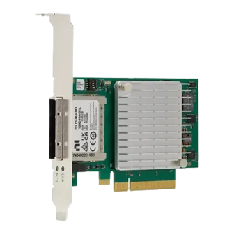
PCIe-8383 Manual 1. Install an ADE, such as LabVIEW or LabWindows™/CVI™. 2. Download the PXI Platform Services installer from ni.com/downloads. Note Refer to the NI Hardware and Software Operating System Compatibility page linked below to confirm which version you need. - Page 18 PCIe-8383 Manual Figure 6. Installing a PCIe-8383 in a Computer 1. PCIe-8383 2. PCI Express x8 Card-Edge Connector 3. PCI Express Slot (x8 or wider) ni.com...
-
Page 19: Installing The Low-Profile Bracket On The Pcie-8383 (Optional)
Using a PCI Express slot wider than x8 may result in negotiation down to x1 width, and therefore limiting bandwidth. This is uncommon in newer PCs. Note The BIOS or motherboard may not support the PCIe-8383 in a slot intended for a graphics card. 1. Power off your computer Caution... - Page 20 6. LEDs 7. Bracket Holes for LEDs 8. Bracket Hole for Connector Shield To install the PCIe-8383 in a host computer that requires a low-profile height card, the front bracket must be replaced with the low-profile bracket included with your kit.
-
Page 21: Connecting The Pcie-8383 To The Chassis
The cables have no polarity, so either end may be connected to either card. 1. Connect one end of the MXI-Express x8 cable to the PCIe-8383. 2. Connect the other end of the cable to the PXIe-8381 board installed in the chassis. -
Page 22: Powering Off The Mxi-Express Gen 2 X8 System
3. Check the LED status on the PCIe-8383 and PXI Express board(s). properly connected and powered up system should report a valid link and power status on all of these boards once the host PC is powered on. Refer to the PCIe-8383 LED Indicators page linked below for more information. -
Page 23: Configuring Your System
PCIe-8383 Manual 1. Power off the host PC. 2. Power off all of the expansion chassis in any order you choose. Configuring Your System The following requires the PXI Platform Services driver and Measurement & Automation Explorer (MAX). For information on configuring your system in MAX, open MAX and navigate to Help »...
Need help?
Do you have a question about the PCIe-8383 and is the answer not in the manual?
Questions and answers