Table of Contents
Advertisement
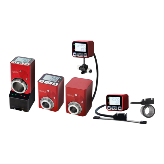
Quick Links
Digital position indicators with fieldbus – user manual
USER MANUAL AND MAINTENANCE GUIDE
DIGITAL ELECTRONIC INDICATORS WITH INDUSTRIAL FIELDBUS
(Profinet, EthernetIP, Ethercat, IO-Link, Modbus)
EP43RS, EP46RS
EP43NET, EP46NET
F4RS-MT, F4RS-M12
F4RS-AM, F4RS-EM43, F4RS-EM46
F4NET-MT, F4NET-M12
F4NET-AM, F4NET-EM43, F4NET-EM46
31/01/2024
EP4_F4 user manual.docx
rev: 1.2
pag 1/38
Advertisement
Table of Contents

Related Manuals for FIAMA EP43RS


Summary of Contents for FIAMA EP43RS
- Page 1 Digital position indicators with fieldbus – user manual USER MANUAL AND MAINTENANCE GUIDE DIGITAL ELECTRONIC INDICATORS WITH INDUSTRIAL FIELDBUS (Profinet, EthernetIP, Ethercat, IO-Link, Modbus) EP43RS, EP46RS EP43NET, EP46NET F4RS-MT, F4RS-M12 F4RS-AM, F4RS-EM43, F4RS-EM46 F4NET-MT, F4NET-M12 F4NET-AM, F4NET-EM43, F4NET-EM46 31/01/2024 EP4_F4 user manual.docx rev: 1.2...
-
Page 2: Manual Purpose
Do not use hydrocarbon solvents (petrol, thinners, etc.): the use of these products could affect the proper function of the instrument. Repairs should be done only and exclusively at the FIAMA technical assistance centre . 1.6 Calibrations and tests It is advisable to calibrate the instrument periodically, once every working year. -
Page 3: Installation
Digital position indicators with fieldbus – user manual 2 Installation Before installing the instrument, heed the following warnings: • Connect the instrument strictly following the instructions of the manual. • It is the responsibility of the user to check, before using, the correct setting of all parameters of the instrument to avoid damage to persons or things. -
Page 4: Configuration Parameters
Digital position indicators with fieldbus – user manual 4 Unit programming 4.1 User menu Note: All the following parameters are also available on the fieldbus. To access programming of the parameters, keep pressed until appears on the display. Then press O 2 times and 3 zeroes will appear. - Page 5 Digital position indicators with fieldbus – user manual VALORE TASTO O TASTO TASTO Not active Not active Not active mm/inch conversion Reset measurement Not active Preset Not active Not active Fast Preset Not active Not active Delayed Reset after 3s (*) Not active Not active Delayed Preset after 3s (*)
-
Page 6: Status Leds
Digital position indicators with fieldbus – user manual Allowed values: • 0 [uses automatic addressing] • [1-255] 4.2.8.2 Modbus version This constant represents the address of the instrument for MODBUS communication with the MASTER unit. Possible values range from 1 to 247. Default value: 1. 4.2.8.3 other versions Unused in IO-Link, profinet e EthernetIP versions. -
Page 7: Battery Replacement
Digital position indicators with fieldbus – user manual 4.4 Position calibration (via keypad) After mounting the instrument on the machine and setting all the parameters, to show the correct measurement on the screen, it is necessary to perform the reset or preset of the position. Position the machine at a point where the correct measurement to be shown is known precisely (e.g., reference stop) or measure the position ... - Page 8 Digital position indicators with fieldbus – user manual 6.1 Modbus The EP4 and F4 series instruments are equipped with serial communication, following the Modbus RTU standard, on an RS485 line. When a power supply is not available, the serial port is not active and the instrument does not respond to the master.
- Page 9 Digital position indicators with fieldbus – user manual 6.1.3 Parameters The parameters that can be read/written through serial communication are listed in the table below. A more detailed explanation of the following parameters is available in the "User Menu" chapter. Indirizzo Parametro Size...
- Page 10 Digital position indicators with fieldbus – user manual 6.1.3.2 Battery status The battery status is indicated by the icon on the display and the Modbus Error register. The Modbus Error register can take the following values to indicate the battery status: •...
- Page 11 Digital position indicators with fieldbus – user manual 6.2 Profinet EP4 and F4 implement the Profinet IRT protocol (conformity class C) for IO-Device units, Ethernet interface. Communication consists of a cyclic part (Status e Target) and an acyclic part (Parameters). To correctly associate EP4 and F4 devices with the appropriate Profinet ProductFamily, please refer to the table below: Codice...
- Page 12 Digital position indicators with fieldbus – user manual Nome Descrizione Ready Device ready Target reached The current position is within the positioning window. Battery low The battery charge level is below a critical threshold: in this case it is necessary to substitute it within 15 days.
- Page 13 Digital position indicators with fieldbus – user manual 6.2.2 Acyclic communication (record data) The EP4 and F4 device uses two groups of acyclic parameters which contain the 11 parameters used for configuration. The first group contains the configuration parameters for visualization (the same parameters which are accessible from the device menu).
- Page 14 (Status e Target) and an acyclic part (Parameters). To correctly associate EP4 and F4 devices with the appropriate EthernetIP ProductFamily, please refer to the table below: Codice Ethernet IP prodName EthernetIP prodCode EP43NET Fiama EP4NET 0x0111 EP46NET Fiama EP4NET 0x0111 F4NET-AM Fiama EP4NET...
- Page 15 Digital position indicators with fieldbus – user manual Status word: when moving from 0 to 1, each bit in this word warns about a different status of the device. The meaning of each status is explained below. Nome Descrizione Ready Device ready Target reached The current position is within the positioning window.
- Page 16 Digital position indicators with fieldbus – user manual 6.3.2 Acyclic communication (record data) The EP4 and F4 device uses two groups of acyclic parameters which contain the 11 parameters used for configuration. The first group contains the configuration parameters for visualization (the same parameters which are accessible from the device menu).
- Page 17 Digital position indicators with fieldbus – user manual To access the previous data structures acyclically, it is necessary to set the msg functions as follows (the example image is taken from the function available for rslogix5000): With this command, the entire parameter block is read from the PLC and saved in the structure set as the 'Destination element'.
- Page 18 Digital position indicators with fieldbus – user manual 6.4 Ethercat communication protocol EP4 and F4 implement the Profinet IRT protocol (conformity class C) for IO-Device units, Ethernet interface. Communication consists of a cyclic part (Status e Target) and an acyclic part (Parameters). The communication (I/O) part of the two product families is identical.
- Page 19 Digital position indicators with fieldbus – user manual 6.4.2 Acyclic communication (SDO) The EP4 and F4 device uses two groups of acyclic parameters which contain the 11 parameters used for configuration. The first group contains the configuration parameters for visualization (the same parameters which are accessible from the device menu).
- Page 20 Digital position indicators with fieldbus – user manual 6.5 IO-Link communication protocol EP4 and F4 implement the IO-Link protoclfor IO-Device units. Communication consists of a cyclic part (Status e Target) and an acyclic part (Parameters). To correctly associate EP4 and F4 devices with the appropriate IO-Link ProductFamily, please refer to the table below: Codice IO-Link device name...
- Page 21 Digital position indicators with fieldbus – user manual Status word: when moving from 0 to 1, each bit in this word warns about a different status of the device. The meaning of each status is explained below. Nome Descrizione Ready Device ready Target reached The current position is within the positioning window.
- Page 22 Digital position indicators with fieldbus – user manual 6.5.2 Acyclical communication (SDO) The EP4 and F4 device uses two groups of acyclic parameters which contain the 11 parameters used for configuration. All of the parameters can be modified in any moment. For a more detailed description of the following parameters please refer to the Programming section.
- Page 23 Digital position indicators with fieldbus – user manual 6.6 LEDs Looking at the displays from the front (battery door side), from left to right, we have the following status LEDs: Link B, Network Status, Module Status, Link A. Note: Communication LEDs are NOT available in the Modbus version. Ethernet IP Ethercat Io-Link...
- Page 24 Digital position indicators with fieldbus – user manual LED Link-A No connection / no No connection / No connection / No connection / no power supply no power supply no power supply power supply Connection Connection Connection established Green established - PORT established - PORT 1 PORT 1 Connection...
-
Page 25: Web Server
Digital position indicators with fieldbus – user manual 6.7 Web server The web server can be reached using the unit's IP address; to know and set the desired address, it is recommended to use one of the applications listed in the utility section. Through the web server, you can configure all the parameters of the device. -
Page 26: Connection Diagram
Digital position indicators with fieldbus – user manual 7 Connection diagram The following chapters contain the connection diagram for the various versions of EP4 and F4. Please refer ONLY to the version in use. 7.1.1 IO-Link version • POWER SUPPLY CONNECTOR M12x1 Male 4 pins A code, IO-Link code DESCRIPTION +24VCC... -
Page 27: Modbus Master
Digital position indicators with fieldbus – user manual 7.1.2 Modbus (RS) version • POWER SUPPLY CONNECTOR 24VDC M12x1 Male 4 pins A code, IO-Link code CONNETTORE M12 CAVO +10÷30VDC BROWN WHITE RS+ positive RS485 serial port YELLOW RS– negative RS485 serial port GREEN Not connected GREY... - Page 28 Digital position indicators with fieldbus – user manual 7.1.3 Profinet/ EthernetIP/Ethercat versions • POWER SUPPLY CONNECTOR 24VDC M12x1 Male 4 pins A code DESCRIPTION 1-4 (*) +24VDC 2-3 (*) (*) The two pins are internally connected together, and it is sufficient to wire only one of the two. •...
- Page 29 Digital position indicators with fieldbus – user manual 8 Display Quota target Quota attuale 1. Absolute mode indicator 2. Low battery indicator: begins to blink when the level of charge is lower than a certain value and when it stays on is is necessary to change the batteries within 15 days. 3.
- Page 30 Digital position indicators with fieldbus – user manual 9 F4 sensors 9.1 Magnetic strip The magnetic strip P50 consists of a magnetized plastic ferrite strip with alternate magnetic poles of 5 mm pitch, carried by a ferromagnetic steel strip. Mechanical protection of the plastic ferrite strip is supplied by a non magnetic steel strip with thickness 0,2mm.
- Page 31 Digital position indicators with fieldbus – user manual 9.3 Magnetic ring mounting (only F4 RS-AM and F4 NET AM) 9.4 SM12 sensor mounting (only F4 RS M12 and F4 NET M12) NB: the magnetic strip must be aligned parallel to the two lateral grooves of the sensor. 31/01/2024 EP4_F4 user manual.docx rev: 1.2...
- Page 32 Digital position indicators with fieldbus – user manual 10 Serial RS485 modbus output connectors (Only EP4xRS ed F4RS x versions) 10.1 M12T (standard) connector 10.2 M12Y (optional) connector 31/01/2024 EP4_F4 user manual.docx rev: 1.2 pag 32/38...
-
Page 33: Overall Dimensions
Digital position indicators with fieldbus – user manual 11 Overall dimensions 11.1 EP43NET 11.2 EP46NET 31/01/2024 EP4_F4 user manual.docx rev: 1.2 pag 33/38... - Page 34 Digital position indicators with fieldbus – user manual 11.3 EP43RS 11.4 EP46RS 31/01/2024 EP4_F4 user manual.docx rev: 1.2 pag 34/38...
- Page 35 Digital position indicators with fieldbus – user manual 11.5 F4RS 31/01/2024 EP4_F4 user manual.docx rev: 1.2 pag 35/38...
- Page 36 Digital position indicators with fieldbus – user manual 11.6 FANET 31/01/2024 EP4_F4 user manual.docx rev: 1.2 pag 36/38...
-
Page 37: Technical Specifications
Digital position indicators with fieldbus – user manual 12 Technical specifications Power supply 10 - 30 Vdc max 100mA Battery 3,6V 1/2 AA format life 6-8 years (depending on use conditions) EP43: Ø14, Ø1/2” Hollow shaft diameter EP46: Ø20, Ø3/4”, Ø25 Max rotation speed 1000 RPM (magnetic ring) 2,5 m/s (magnetic strip) - Page 38 Tel. (+39) 0521.672.341 – Fax. (+39) 0521.672.537 – e-mail: info@fiama.it – www.fiama.it FIAMA srl is not responsible for any damage to persons or things caused by tampering and improper use and in any cases that are not compatible with the features of the instrument.
Need help?
Do you have a question about the EP43RS and is the answer not in the manual?
Questions and answers