Advertisement
Quick Links
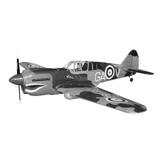
CURTISS P-40
VQAO20U / VQA021F / VQA0201B / VA022C
INSTRUCTION MANUAL / MONTAGEANLEITUNG
TECHNISCHE DATEN
Spannweiter
Lange
Elektroantrieb
870 Watt Brushless Motor
Verbrennerantrieb
Fernsteuerung
WARNING! This radio controlled model is NOT a toy. If modified or flown carelessly it could go out of controll and
cause serious human injury or property damage. Before flying your airplane, ensure the air field is spacious enough.
Always fly it outdoors in safe areas and seek professional advice if you are unexperienced.
ACHTUNG! Dieses ferngesteuerte Modell ist KEIN Spielzeug! Es ist für fortgeschrittene Modellflugpiloten bestimmt,
die ausreichende Erfahrung im Umgang mit derartigen Modellen besitzen Bei unsachgemäßer Verwendung kann
hoher Personen- und/oder Sachschaden entstehen. Fragen Sie in einem Modellbauverein in Ihrer Nähe um
professionelle Unterstützung, wenn Sie Hilfe im Bau und Betrieb benötigen. Der Zusammenbau dieses Modells ist
durch die vielen Abbildungen selbsterklärend und ist für fortgeschrittene, erfahrene Modellbauer bestimmt.
RADIO CONTROL MODEL
1570mm
1360mm
10cc 2-T / 15cc 4-T
6 Kanal / 7 Servos
SPECIFICATIONS
Wingspan
Length
Electric Motor
870 Watt Brushless Motor
Glow Engine
Radio
6 Channel / 7 Servos
1570mm
1360mm
.60 2-T / .90 4-T
Advertisement

Related Manuals for Radio control model CURTISS P-40


Summary of Contents for Radio control model CURTISS P-40
- Page 1 RADIO CONTROL MODEL CURTISS P-40 VQAO20U / VQA021F / VQA0201B / VA022C INSTRUCTION MANUAL / MONTAGEANLEITUNG SPECIFICATIONS TECHNISCHE DATEN Wingspan 1570mm Spannweiter 1570mm Length 1360mm Lange 1360mm Electric Motor 870 Watt Brushless Motor Elektroantrieb 870 Watt Brushless Motor Glow Engine .60 2-T / .90 4-T...
- Page 2 REQUIRED FOR OPERATION (Purchase separately) BENOTIGTE KOMPONENTEN FUR DEN ABFLUG (Nicht enthalten) 12x6 for .60 - 2 cycle engine 13x7 for .90 - 4 cycle engine 14X8 for Quantum 4120/07 BOOTS 60 Phoenix-60 Brushless Motor Control or equivalent. Extension for aileron Flap and retract servo.
- Page 3 Joining the wing / Flachenverbindung TOP VIEW / AUFSICHT 1- Using a pencil, mark the center of the brace. 2- Trial fit the wing joiner into one of the wing panels. It should insert smoothly up to the center line marked above. 3- Slide the other wing half onto the dihedral brace until the wing panel meet.
- Page 4 WING - BOTTOM VIEW Retract landing gear / Einziehfahrwerk UNTERSICHT VQ-AR07 - 160227 (Purchase separately) Retract servo 1/8x15/32” (3x12mm) screw E-ring Pillow ball STEP STEP STEP RETRACT LANDING GEAR INSTALLATION Fixed gear / Starres Fahrwerk WING - BOTTOM VIEW UNTERSICHT Main gear (left) Plastic strapX4 Main gear (right)
- Page 5 ABS Shield WING - BOTTOM VIEW UNTERSICHT “R” for the right half wing “L” for the left half wing WING - BOTTOM VIEW / Flap, Aileron servo / Flap, querruder servo UNTERSICHT Aileron extension cord Aileron extension cord exit Aileron servo hatch Flap servo hatch flap extension cord...
- Page 6 1-Trial fit the horizontal stabilizer into the fuselage. Horizontal stabilizer / Leiwerke Use a pencil to carefully trace around the top and bottom of the horizontal stabilizer where it meets the fuselage. 2-Remove the horizontal stabilizer from the fuselage, carefully cut away the covering inside the lines which were marked in steep 1.
-
Page 7: Front View
5/64”(2mm) collar Tail gear / Heckspornrad FUSELAGE - BOTTOM VIEW UNTERSICHT 3x12mm screw Tail gear mount 1-Place the tail gear mount on the bottom 1/8x15/32” Tail gear horn of the fuselage as show, mark the (3x12mm) screw mounting hole positions with a pencil....2 2-Remove the tail gear mount from the Tail gear horn... -
Page 8: Brushless Motor
Brushless motor Firewall A=A’ A’ 135mm (5-5/16”) SIDE-VIEW FRONT-VIEW Bolts, nuts and washer are not supplied Fuel tank / Treibstofftank To muffler Filler tube Rubber stopper After confirming the direction, insert this assembly, clunk end first, into the fuel tank Fuel tube Stopper To engine... - Page 9 Linkages / Anlenkungen Connector ..3 Connector Connector Rudder Elevator pushrod pushrod ..1 Rudder servo Elevator servo Fuel tank FUSELAGE - BOTTOM VIEW UNTERSICHT ABS Shield FUSELAGE - BOTTOM VIEW UNTERSICHT Cut away only the covering 1-Using the ABS shield as a template, trace around the outside edge of the ABS shield, and then remove it.
- Page 10 Canopy / Kabinenhaube 2x10mm screw ....4 1.5mm Decor / Aufkleber CHINESE AIR-FORCE VQA022C AVG CHECKER TAIL VERSION VQA020B US.ARMY Note: Cut out the stickers and apply them in the proper area. Do not peel the backing paper off all at once. Peel off one corner of the backing and cut off with scissors.
- Page 11 DO NOT try to fly an out-of-balance model ! Balance / Schwerpunkt Note: If necessary, move the battery pack or add weight to either the tail 4”~4-1/8” or nose until the correct balance is achieved. (100~105mm) Wing center section Control surface / Ruderausschlage 1-23/64”(35 mm) 13/32”(10mm) 1-23/64”(35 mm)
Need help?
Do you have a question about the CURTISS P-40 and is the answer not in the manual?
Questions and answers