Advertisement
Quick Links
Radio control model / Flugmodel
INSTRUCTION MANUAL / Montageanleitung
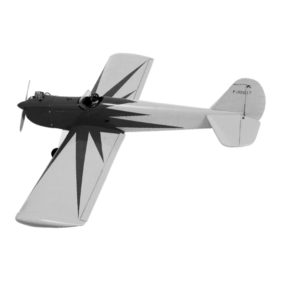
SPACE WALKER
SPECIFICATION
Wingspan
Electric Motor
Glow Engine
Radio
TECHNISCHE DATEN
Spannweiter
Elektroantrieb
Verbrennerantrieb
Fernsteuerung
WARNING! This radio controlled model is NOT a toy. If modified or flown carelessly it could go out of controll and
cause serious human injury or property damage. Before flying your airplane, ensure the air field is spacious enough.
Always fly it outdoors in safe areas and seek professional advice if you are unexperienced.
ACHTUNG! Dieses ferngesteuerte Modell ist KEIN Spielzeug! Es ist für fortgeschrittene Modellflugpiloten bestimmt,
die ausreichende Erfahrung im Umgang mit derartigen Modellen besitzen Bei unsachgemäßer Verwendung kann
hoher Personen- und/oder Sachschaden entstehen. Fragen Sie in einem Modellbauverein in Ihrer Nähe um
professionelle Unterstützung, wenn Sie Hilfe im Bau und Betrieb benötigen. Der Zusammenbau dieses Modells ist
durch die vielen Abbildungen selbsterklärend und ist für fortgeschrittene, erfahrene Modellbauer bestimmt.
1580mm
870 Watt
7.5cc 2T / 8.5cc 4T
5 Channel / 5 Servos
1580mm
870 Watt
7.5cc 2T / 8.5cc 4T
5 Kanal / 5 Servos
VQA017 (Single seat)
VQA018 (Two seat)
Advertisement

Related Manuals for Radio control model VQA017


Summary of Contents for Radio control model VQA017
- Page 1 Radio control model / Flugmodel INSTRUCTION MANUAL / Montageanleitung SPACE WALKER VQA017 (Single seat) VQA018 (Two seat) SPECIFICATION Wingspan 1580mm Electric Motor 870 Watt Glow Engine 7.5cc 2T / 8.5cc 4T Radio 5 Channel / 5 Servos TECHNISCHE DATEN Spannweiter...
-
Page 2: Conversion Table
REQUIRED ITEMS / Zum Betrieb wird benotigt 11x6 for 7.5cc - 2 cycle engine 11x7 for 8.5cc - 4 cycle engine Extension for aileron 12x7~ 13X6 for Brushless Motor servo 60A Brushless ASC 60A Brushless Regler 7.5cc 2T 8.5 ~ 10cc 4T Minimum 4 channel radio for airplane with 4 servos .Motor control x1 .Aileron x2... - Page 3 Cut the hole for the aileron servo extension exit. Adhesive tape Thread for aileron servo extension 1-Cut the hole on the top of the wing halves (left and right) for the aileron servo extension exit. Remove the thread out of the hole and secure it WING TOP-VIEW in place with adhesive tape.
- Page 4 All holes for landing gear installation are pre-drilled at factory. 2x3mm ....8 .....4 3x10mm .....4 .......8 .....2 2.5mm Wheel pant BOTTOM VIEW...
- Page 5 Full the elevator out of the horizontal stabilizer. Cut away only the film both side Trial fit the horizontal stabilizer in place. Check the alignment of the horizontal stabilizer. If the parts will join, but with a gaps, sand or trim the parts a little at a time until the parts meet exactly with no gaps.
- Page 6 Apply 5 min. Petroleum jelly Epoxy both the top and bottom. ELEVATOR STABILIZER Hinge Control horn ....2 2x15mm screw ..4 Hinge Line/Control horn Alignment Attach the control horn on the elevator. * WARNING: When removing any covering from the airframe, please ensure that you secure the cut edge with CA or similar cement.
-
Page 7: Bottom View
Collar 1/8(3mm) screw 0.5~0.6in. 12~15mm 0.3in. 1/16 1.5mm BOTTOM VIEW 1/16 3x12..2 1.5mm ......1 ......1 3x20mm Screw Washer 3x20mm screw 4.9”(124mm) ...4 3mm Washer ....4 In case of two-stroke engine 3mm Nut Washer .....4 1/8(3mm) Nut 4mm blind nut Align the mark on both mounts with the mark on the fuselage 11/64... - Page 8 Align the mark on both mounts with the mark on the fuselage 4mm blind nut Mark Side line Tail pipe 4x20mm screw Align the crankshaft of the engine with 11/64 4.3mm the side line In case of four-stroke engine Silicon tube must be purchased separately Carefully install the fuel tank...
-
Page 9: Elevator Servo
Using a aluminum motor mounting plate as a template, mark the plywood motor mounting BRUSHLESS MOTOR plate where the four holes are to be drilled (2). Remove the aluminum motor mounting plate and drill a 1/8”(3mm) hole through the plywood at each of the four marks marked . - Page 10 Li-Po Battery Stand Li-Po Battery (Plywood) Magnetic top hatch Carefully install the Li-Po battery pack to ensure that they will not shift during flight. Shift the location of the receiver and batter pack aneeded to obtain the specified CG Carefully install the receiver and battery pack to ensure that they will not shift during flight...
- Page 11 2x5mm screw 5/64 2.mm .....8 3 x10mm ......16 2.5x10mm ......4 2 x5mm ......4 2.5x10mm screw 3x10mm screw Cut away the cowl 5/64 to clear the engine 2.mm head Control surface 1”(25mm) 21/64” 7/16” (8mm) (11mm) 7/16” 21/64” 1”(25mm) (8mm) (11mm) AILERON STROKE RUDDER STROKE ELEVATOR STROKE...
-
Page 12: Cautions For Safety
Check the operation and direction of the elevator, rudder, ailerons and throttle: AILERON RUDDER ELEVATOR CAUTIONS FOR SAFETY Ensure the airfield is spacious enough. Ensure the spinner and propeller are securely attached. Immediately disure defective propeller as well as deformed spinners.
Need help?
Do you have a question about the VQA017 and is the answer not in the manual?
Questions and answers