
Subscribe to Our Youtube Channel
Related Manuals for Terex PT-50


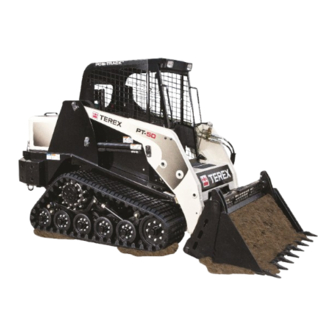
Summary of Contents for Terex PT-50
- Page 1 C o m p a c t Tr a c k L o a d e r Operation and Maintenance Manual Version: EN Edition: 2010-04 Part Number: 2030-613 Valid From Serial No: DTC 03133 (50) DTE 02742 (60) Original Instructions PT-50/60...
-
Page 3: Table Of Contents
CONTENTS Page Introduction ..........2 Safety ............5 Technical Data..........31 Machine Description / Controls..... 37 Operation ............. 45 Transportation ..........55 Maintenance ..........61 California Proposition 65 ......81 Service Log ..........82... -
Page 4: Introduction
PIN when making inquiries in regards to parts, service, or warranty. 1.2 Introduction Thank you for purchasing a Terex Compact Track Loader. We are confident that the machine you have chosen will provide excellent performance and effi- cient operation. The information contained in this manual is intended to provide the operator with all necessary information for the proper use of the machine. - Page 5 1.5 Warranty Your Terex PT-50/60 is warranted under the Terex Compact Track Loader and Utility Vehicle Standard Limited New Product Warranty (“Warranty”). A copy of the Warranty certificate is included with this manual and is also available from your...
-
Page 7: Safety
2 SAFETY Page 2.1 Safety Alert System ........ 7 2.2 Pictograms..........8 2.3 Safety Symbols ........10 2.4 Safety Signs ........... 14 2.5 General Notes ........16 2.6 Personal Protection Equipment....17 2.7 Danger Zone .......... 17 2.8 Operation ..........18 2.9 Stability.......... -
Page 9: Safety Alert System
2 SAFETY 2.1 Safety Alert System This symbol means: Attention! Be alert! Your safety is involved! The safety alert symbol is used to alert you to potential personal injury hazards. Obey all safety messages that follow this symbol to avoid possible injury or death. -
Page 10: Pictograms
2 SAFETY 2.2 Pictograms Symbol Description Engine Pre-heat Battery Engine Speed: Fast Transmission Range: High Engine Speed: Slow Transmission Range: Low Windshield Wiper Beacon Light Oil Pressure Engine Coolant Temperature Hydraulic Oil Temperature Air Conditioning... - Page 11 2 SAFETY Symbol Description Work Lights Bucket Positioning...
-
Page 12: Safety Symbols
2 SAFETY 2.3 Safety Symbols Hazard Avoidance Description Hazard: Skin Oil Injection Escaping fluid under pressure can penetrate skin, causing serious injury. Avoidance: • Relieve internal pressure before disconnecting any line or fitting. • Keep away from leaks or pin- holes. - Page 13 2 SAFETY Hazard Avoidance Description Hazard: Explosion/Burn Will cause death, burns or blind- ness due to ignition of explosive gasses or contact with corrosive acid. Avoidance: • Keep all flames/sparks away! • No Smoking! • Read and understand all manu- als prior to operation.
- Page 14 2 SAFETY Hazard Avoidance Description Hazard: Entanglement Rotating Parts can cause personal injury. Avoidance: Keep away from fan while the engine is running. Stop the engine and remove ignition key before servicing the machine. Hazard: Rollover / Ejection Avoidance: Carry loads low, keep heaviest end of machine uphill at all times while operating on inclines.
- Page 15 2 SAFETY Hazard Avoidance Description Hazard: Crush Serious injury or death can result from contact with moving lift arm or attachment. 2030-417 Avoidance: Keep clear of lift arms and attachments. Hazard: Attention, Your safety is involved! Avoidance: Read and understand the operator’s manual before using or maintaining the machine.
-
Page 16: Safety Signs
2 SAFETY 2.4 Safety Signs The safety signs are located in/on the machine as indicated. (Descriptions of the symbols are provided in section 2.3) WARNING • Relieve internal pressure before disconnecting any line or fitting. • Keep away from leaks or pinholes. •... - Page 17 2 SAFETY Note: If any of the safety signs shown in this section are missing or damaged, contact your dealer to obtain a replacement. WARNING WARNING • Relieve internal pressure before disconnecting any line or fitting. • Keep away from leaks or pinholes. •...
-
Page 18: General Notes
2 SAFETY 2.5 General Safety Notes • Read and understand all safety signs and operator’s manuals prior to opera- tion. • Never jump off of the machine. Instead use the hand holds and step designed for entering and exiting the machine. Face the machine and use three points of contact to ensure your safety. -
Page 19: Personal Protection Equipment
2 SAFETY 2.6 Personal Protection Equipment The machine is designed to accommodate and protect an operator during opera- tion from foreseeable injury when used as intended and when equipped prop- erly for the task(s) being performed. Operators should not wear rings, scarves, open jackets, and should ensure that all clothing is tightly secured. -
Page 20: Operation
2 SAFETY 2.8 Operation Earth moving machines are only to be operated and serviced by individuals who • are physically and mentally able to operate and / or service the machine in a safe manner. • have been instructed in the proper operation or maintenance of the machine and have demonstrated competence in these areas. -
Page 21: Stability
• Do not exceed the operating capacity of the machine. • Never operate the PT-50/60 on an incline in excess of 15°. • Do not make sudden changes in direction, move slowly, and always carry loads low to maximize machine stability. -
Page 22: Fire Prevention
2 SAFETY 2.11 Fire Prevention Compact Track loaders have components that operate at high temperatures. It is important to observe all inspection, operation and maintenance guidelines to min- imize the possibility of fire. • Turn the engine off when refueling. •... -
Page 23: Crush / Burn Avoidance
2 SAFETY 2.12 Crush and Burn Avoidance • Do not work under the lift arms unless they are resting safely on the ground or supported by the lift arm brace. • Do not use any restraining devices such as cables or chains that are damaged or do not have sufficient carrying capacity. -
Page 24: Placing Into Operation
2 SAFETY 2.13 Placing into Operation • Every time before placing the machine into operation, perform a thorough walk-around inspection of the machine. • Check the machine for loose pins, cracks, tears, wear, leaks and deliberate damage. • Never place a damaged machine into operation. •... -
Page 25: Jobsite Safety
2 SAFETY 2.15 Jobsite Safety • Before beginning work, become acquainted with any special features or requirements of the work site. These may include, for example, obstructions in the work area, the carrying capacity of the ground and requirements to close the work site off from public traffic. -
Page 26: Parking The Machine
2 SAFETY 2.16 Parking the Machine • If possible, turn the machine off only on an even and solid surface. • Lower the lift arms to the frame stop and rest the bucket on the ground. • Turn off the engine as described in the operating instructions. •... -
Page 27: Transporting
2 SAFETY 2.18 Transporting the Machine • Use only suitable transport and lifting equipment with sufficient carrying capacity. • Load the machine on firm and level ground. • Before driving onto the ramps, clean them and the machine tracks of any materials that may cause slippage (snow, ice, sludge, etc.). -
Page 28: Maintenance
Do not work on or under any machine that is supported only by a hydraulic jack or hoist. Always use mechanical supports to ensure that the machine will not fall. Terex jack stands work well to support the machine while per forming maintenance or repair work. - Page 29 Do not use flammable liquids to clean the machine. • Perform tasks on the machine that involve welding or grinding only if approved by Terex. Clean the machine and the work area of dust and any combustible materials before welding or grinding to avoid fire or explosion. •...
-
Page 30: Battery
2 SAFETY • Do not attempt to lift heavy parts. Use work aids with sufficient carrying capacity designed for that purpose. Fasten and secure individual parts and large assemblies carefully on lifting equipment to minimize the possibility of objects falling. Use only suitable lifting equipment with no technical defects. Do not work under suspended loads. -
Page 31: Hydraulic Lines / Hoses
2 SAFETY 2.21 Hydraulic Hoses/Lines • Repairs to hydraulic hoses and hydraulic hose lines are forbidden! These repairs must be performed by trained personnel. • All hoses, hose lines and screw connections must be checked regularly, at least once a year, for leaks and externally visible damage! Replace any damaged parts immediately! Oil spraying out can cause injuries and burns. -
Page 33: Technical Data
3 TECHNICAL DATA Page 3.1 General Structure ........33 3.2 Views ............. 34 3.3 Engine............ 34 3.4 Electrical System........34 3.5 Undercarriage ........34 3.6 Transmission .......... 35 3.7 Auxiliary Hydraulics ........ 35 3.8 Ground Pressure ........35 3.9 Operating Specifications......35 3.10 Service / Refill Capacities..... -
Page 35: General Structure
3 TECHNICAL DATA 3.1 General Structure Bucket Lift Arm Operator Enclosure (R.O.P.S./F.O.P.S. approved) Hydraulic Oil (fill location) Diesel Fuel (fill location) Hood (engine cover) Engine Drive Motor and Sprocket Undercarriage 10. Quick Attach 11. Product PIN Plate (beside operator seat, inside enclosure) -
Page 36: Views
59 in. 15 in. 1499 mm 381mm 66 in. 100 in. 1676 mm 2540 mm 128 in. 3251 mm 3.3 Engine PT-50 [PT-60] Make Perkins Perkins Type 404D-22 404D-22T Design 4 cylinders in line 4 cylinders in line (turbo) Displacement 134 in. -
Page 37: Transmission
Operating capacity (35% ti 1330 lb (603 kg) 1330 lb (603 kg) Note: The Maximum Gross Vehicle Weight of the PT-50/60 is not to exceed 8500 lb. (3856 kg). This excludes an operator, but does include accessories, attach- ments and material being carried. -
Page 38: Fluid Specifications
3 TECHNICAL DATA 3.11 Fluid Specifications (applies to both machines) Specifications Specification/standard Designation Fuel Diesel Fuel EN590 or ASTM D975 1-D / 2-D Engine Oil Engine Oil SAE 10W-30 (API CH-4) Engine Coolant Coolant Antifreeze/Water w/SCA additive Hydraulic Oil Hydraulic Oil Chevron-Rykon MV or equivalent Lubricating Points MP Grease... -
Page 39: Machine Description / Controls
4 MACHINE DESCRIPTION / CONTROLS Page 4.1 Display Elements........39 4.2 Controls..........40 4.3 Throttle........... 41 4.4 Two Speed ..........41 4.5 Bucket Positioning........41 4.6 Auxiliary Hydraulics ........ 42 4.7 Electric Attachment Control ....43 4.8 Emergency Exits........43... -
Page 41: Display Elements
4 MACHINE DESCRIPTION / CONTROLS 4.1 Display Elements Learn the location and function of these items prior to operation. Switch Panels 1 - Work lights 2 - Heater fan (optional) 3 - Front wiper (optional) 4 - Beacon light (optional) 9 - Auxiliary hydraulics 10 - Bucket positioning (optional) 11 - Power Q/A (optional) -
Page 42: Controls
4 MACHINE DESCRIPTION / CONTROLS 4.2 Controls The PT-50/60 has two hydraulic pilot joystick controls. The joysticks are used to control machine speed and direction as well as lift arm and bucket functions. 4.2.1 Lift Arm Control The lift arm joystick is used to control the lift arms, bucket, and to engage the float function. -
Page 43: Throttle
4.5 Bucket Positioning (optional) The PT-50/60 machines can be equipped with feature commonly referred to as “bucket positioning”. The bucket positioning system does not automatically level your attachment. Instead, it will maintain the current angle of the quick attach (relative to level) throughout the upward cycle of the lift arms. -
Page 44: Auxiliary Hydraulics
4 MACHINE DESCRIPTION / CONTROLS 4.6-1 4.6-2 4.6 Auxiliary Hydraulics The PT-50/60 models come equipped with an auxiliary hydraulic system designed to power approved hydraulic attachments. To operate, connect the attachment to the quick couplers (fig. 4.6-1). To release resid- ual pressure in the system, press the button labeled 1 (fig. -
Page 45: Electric Attachment Control
4.7-1 4.7-2 4.7 Electric Attachment Control Attachments for the PT-50/60 are controlled by pressing various buttons on the machines joysticks. Most attachments are controlled hydraulically, but some require both hydraulic and electrical inputs. The 4 buttons on the left joystick (4.7-1) send electrical current to the receptacle on the lift arms (4.7-2). -
Page 47: Operation
5 OPERATION Page 5.1 General Information........ 47 5.2 Pre-Operation Safety Checklist....47 5.3 Starting Procedure ......... 48 5.4 Surface Preservation ......49 5.5 Filling the Bucket ........49 5.6 Grading ..........50 5.7 Leveling ..........50 5.8 Loading ..........51 5.9 Fastening Attachments ...... -
Page 49: General Information
5 OPERATION 5.1 General Information Operating a Terex Compact Track Loader is intended to be as safe and simple as possible. This section expands on the machine controls portion of the manual and also covers safe operation procedures to follow while operating. -
Page 50: Starting Procedure
5 OPERATION 5.3-1 5.3-2 5.3 Starting Procedure Before starting the engine, perform the pre-operation safety checklist. Once com- plete, you may proceed by following this procedure: Enter machine with lift arms all the way down. Maintain three points of contact with the machine (fig. 5.3-1). Sit down into the operator’s seat, fasten seat belt, then lower lap bar into position. -
Page 51: Surface Preservation
5 OPERATION 5.4 Surface Preservation Terex Compact Track Loaders are 5.4-1 designed to produce minimal ground disturbance while operat- ing on finished surfaces like turf, however, care should be taken while operating on these surfaces to prevent blemishes from occur- ring. -
Page 52: Grading
5 OPERATION 5.6 Grading Steps: (see illustration) Lower the lift arms until they rest on the frame. Tilt the bucket slowly forward until the cutting edge engages the ground. Drive the machine forward making slight bucket angle adjustments to vary cut depth as necessary. -
Page 53: Loading
5 OPERATION 5.8 Loading Steps: (see illustration) Engage the bucket positioning function (if equipped), then raise the lift arms upward until the bottom of the bucket clears the side of the truck bed or trailer. Once clear, drive the machine forward until the pivot point of the bucket clears the bed side. -
Page 54: Unfastening Attachments
5 OPERATION 5.10 Unfastening Attachments (see also section 5.11) Lower the lift arms so that the attachment is just barely off of the ground. Pull the locking levers on the quick attach mechanism upwards and toward the outside of the machine to unlock the attachment. 5.10-1 unlock Lay the attachment gently onto the ground... -
Page 55: Operation On Inclines
Even with these capabilities, caution should always be exercised while operating the machine on an incline. Never operate the PT-50/60 on an incline in excess of 15°. Do not make sudden changes in direction, move slow- ly, and always carry loads low to maximize machine stability. -
Page 56: Lift Arm Brace
5 OPERATION 5.14 Lift Arm Brace When the lift arms must be left in the raised position, the lift arm brace must be engaged. To install: Lower the lift arms, remove any attachments and park the 5.14-1 machine on firm and level ground. -
Page 57: Transportation
6 TRANSPORTATION Page 6.1 Transporting ........... 57 6.2 Towing / Retrieving......... 57 6.3 Loading / Unloading Procedure ..... 58 6.4 Lifting Procedure........59... -
Page 59: Transporting
6.2 Towing/Retrieving In the event that the PT-50/60 needs to be towed or retrieved, it will not roll freely. You must drag it to safety. Use only chains that are rated for pulling a machine of this size and weight. Attach these chains to at least two of the D- rings in the front or rear of the machine. -
Page 60: Loading / Unloading Procedure
6 TRANSPORTATION 6.3 Transport Loading / Unloading procedure Load the machine only on firm and level ground. Before driving onto the ramps, clean them and the machine tracks of any materials that may cause slippage (snow, ice, sludge, etc.). Properly align the machine with the loading ramp. Have a guide give the machine operator any necessary signs to maximize safety during loading. -
Page 61: Lifting Procedure
6 TRANSPORTATION 6.4 Lifting Procedure At times, the PT-50/60 may need to be lifted with the optional lift kit. This section addresses the proper procedures and attach- ment points for these activities. Lifting Lifting the machine from above should only 6.4-1... -
Page 63: Maintenance
7 MAINTENANCE Page 7.1 General ..........63 7.2 Care and Cleaning........63 7.3 Maintenance Intervals ......64 7.4 Lubrication Points........65 7.5 Engine Oil Check ........66 7.6 Engine Oil Change........67 7.7 Hydraulic Oil Change ......68 7.8 Hydraulic Filter Change ......69 7.9 Accessory Belt........ -
Page 65: General
7 MAINTENANCE 7.1 General The operating condition and life expectancy of a machine is largely influenced by care and maintenance. For this reason, it is in every machine owner’s interest to perform the specified maintenance work and comply with the service intervals. This chapter describes periodic maintenance, inspection and lubricating tasks. -
Page 66: Maintenance Intervals
7 MAINTENANCE 7.3 Maintenance Intervals 7.3-1 Daily Maintenance Tasks Daily Page Check hydraulic oil level (figure 7.7-3, p-68) Check engine oil level Check fuel level (gauge on instrument panel) Check fan belt tension / condition Check track tension / condition Check for proper control operation Check for proper switch and lighting operation Check / clean air cleaner elements... -
Page 67: Lubrication Points
7 MAINTENANCE 7.4 Lubrication Points The illustration below shows the location of grease points found on the left side of the machine. Identical points also exist on the opposite side of the machine. Lubricate all points daily, prior to operation. -
Page 68: Engine Oil Check
7 MAINTENANCE 7.5 Engine Oil Check Park the machine on level ground, lower the lift arms, stop the engine and remove the key. Open the hood to gain access to the engine compartment. Locate and remove the engine oil dipstick (1) from its tube. (fig. 7.5-1) 7.5-1 Wipe the dipstick with a clean shop cloth and reinsert it into the tube... -
Page 69: Engine Oil Change
7.6-2 7.6 Engine Oil Change Regular oil changes are necessary to maintain a strong running engine. Terex rec- ommends a normal oil change interval of 250 hours or every six months. Allow the machine to cool prior to service. Wear safety glasses, safety gloves and any other items necessary to ensure your safety while performing maintenance or service. -
Page 70: Hydraulic Oil Change
7 MAINTENANCE 7.7 Hydraulic Oil Change 7.7-1 7.7-2 The hydraulic oil should be changed 7.7-3 every 500 service hours. Before begin- ning the procedure, make sure the machine is in a clean working environ- ment. Take any necessary measures to prevent dirt or debris from entering the hydraulic system. -
Page 71: Hydraulic Filter Change
The engine uses a belt to drive accessories like the alternator, water pump, and cooling fan. Belts typically stretch and wear during their service life. As a result, the accessory belt on the PT-50/60 should be visually inspected daily for tension, condition, and presence prior to operating your machine. -
Page 72: Water Separator
7 MAINTENANCE 7.10 Water Separator The water separator (fig. 7.10-1), located on the left side of the engine) removes water from the fuel supply as the engine runs. Drain the water separator daily to maintain proper function. 7.10-1 To drain the water separator: With the engine off and cool, and key removed from the ignition, open the hood at the rear of the machine to access the water separator. -
Page 73: General Undercarriage
The undercarriage assemblies typically operate in harsh working conditions. They work in mud, gravel, debris and various other abrasive materials during operation. Terex recommends a daily inspection of the undercarriage assemblies and clean- ing if necessary. Materials that are particularly sticky or abrasive like clay, mud, or gravel should be cleaned from the undercarriages often to minimize component wear. -
Page 74: Track Tension Adjustment
7 MAINTENANCE 7.13-2 7.13-1 7.14 Track Tension Adjust With the engine off and the key removed from the ignition, locate jam nut on track tension device and clean the threads thoroughly before proceeding. (fig. 7.14-1). 7.14-1 Using a wrench, loosen the jam nut on the track tension device. -
Page 75: Drive Sprocket Rollers
Visually inspect rollers every 50 hours and replace any that show signs of crack- ing or wear-through. Drive sprocket removal and roller / pin replacement should be performed by your local Terex dealer. -
Page 76: Air Cleaner Removal / Inspection
7 MAINTENANCE 7.16 Air Cleaner Removal / Inspection The air cleaner is one of the most important maintenance items on the machine. Regular inspection and replacement is necessary to ensure proper performance and to prolong engine life. Inspect the air cleaner elements daily. If damaged or heavily soiled, clean or replace the elements. -
Page 77: Air Cleaner Cleaning
7 MAINTENANCE 7.17 Air Cleaner Cleaning procedure Remove loose dirt from the element with compressed air or water hose. • Compressed air: 100 psi (690 kPa) max. 1/8 in. (.32cm) diameter nozzle at least 2 in. (5cm) away from the filter element. •... -
Page 78: Radiator Oil Cooler Cleaning
7 MAINTENANCE 7.18 Radiator / Oil Cooler Cleaning Procedure The radiator and oil cooler must be clean to ensure proper operation. Engine and hydraulic system over- heating, damage and even failure can result if the radiator/oil cooler is 7.18-1 not kept clean. A pressure washer or compressed air nozzle work well to blow debris clear of the fins in the oil cooler and radiator. -
Page 79: Chassis Cleaning
7 MAINTENANCE 7.20 Chassis Cleaning Procedure Periodic cleaning of the chassis area beneath the cab and engine com- partment is also necessary to main- tain safe operation. Clean as neces- sary. (fig. 7.20-1) 7.20-1 To clean the chassis/engine: With the engine off and cool and the key removed from the ignition, remove the belly pans on the underside of the machine. -
Page 80: Electrical System
7 MAINTENANCE 7.21 Electrical System PT-50/60 ELECTRICAL PANEL AUX LDR 1 AUX LDR 2 AUX LDR 3 AUX LDR 4 40 A . RELAY 40 A . RELAY 40 A . RELAY 40 A . RELAY # 87417B # 87417B... -
Page 81: Storage
7 MAINTENANCE 7.22 Storage It may be necessary to store your Terex Compact Track Loader for an extended period of time. Perform the following tasks to prepare the machine for storage. 7.22.1 Storage Preparation • Thoroughly clean the machine (inside and out) including the engine compart- ment and underbody. - Page 82 7 MAINTENANCE 7.22.2 Removal From Storage Perform the following tasks to remove the Terex Compact Track Loader from stor- age and return to operating condition. Return to Operating Condition: • Remove protective lubricant from cylinder rods. • Lubricate all chassis, loader and undercarriage points.
-
Page 83: California Proposition 65
California (U.S.A.) state law stipulates that manufacturers of machines operated within its borders must provide a clear warning to customers regarding exposure to substances commonly associated with the machine that are recognized by the state as harmful. Terex/ASV complies with this requirement by providing the following information. CALIFORNIA... -
Page 84: Service Log
SERVICE LOG Hours Service Performed Notes... - Page 85 SERVICE LOG Hours Service Performed Notes...
- Page 86 Terex Construction Americas 8800 Rostin Road Southaven, MS 38671 (888)-201-6008 (662)-393-1800 www.terex.com...
Need help?
Do you have a question about the PT-50 and is the answer not in the manual?
Questions and answers