Sign In
Upload
Download
Table of Contents
Contents
Add to my manuals
Delete from my manuals
Share
URL of this page:
HTML Link:
Bookmark this page
Add
Manual will be automatically added to "My Manuals"
Print this page
×
Bookmark added
×
Added to my manuals
Manuals
Brands
Olmo Manuals
Air Conditioner
Premion Series
Installation and operation manual
Olmo Premion Series Installation And Operation Manual
Hide thumbs
1
2
3
4
5
6
7
8
9
10
11
12
13
14
15
16
17
18
19
20
21
22
23
24
25
26
27
Table Of Contents
28
29
30
31
32
33
34
35
36
37
38
39
40
41
42
43
44
45
46
47
48
49
50
51
52
53
54
55
56
57
page
of
57
Go
/
57
Contents
Table of Contents
Troubleshooting
Bookmarks
Table of Contents
Table of Contents
Safety Instructions
Preparation before Use
Safety Precautions
Installation Instructions
Installation Diagram
Select the Installation Locations
Indoor Unit Installation
Maintenance
Protection
Troubleshooting
Identification of Parts
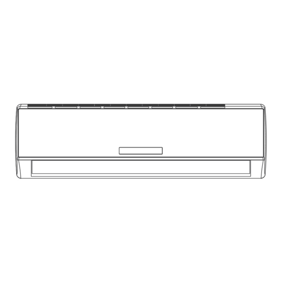
Indoor Unit
Outdoor Unit
Display Introduction
Installation Instructions
Installation Diagram
Select the Installation Locations
Connecting of the Cable
Wiring Diagram Outdoor
Unit Installation Air
Purging
Advertisement
Quick Links
Download this manual
ПОСІБНИК З
UA
ВСТАНОВЛЕННЯ
ТА ЕКСПЛУАТАЦІЇ
Premion Series
Premion Series
OSH-09FWH
OSH-09FWH
OSH-12FWH
OSH-12FWH
OSH-18FWH
OSH-18FWH
OSH-24FWH
OSH-24FWH
Ця інструкція з експлуатації вміщує важливу інформацію та рекомендації,
які необхідно виконувати для тривалої та якісної роботи кондиціонера.
Table of
Contents
Previous
Page
Next
Page
1
2
3
4
5
Advertisement
Table of Contents
Need help?
Do you have a question about the Premion Series and is the answer not in the manual?
Ask a question
Questions and answers
Related Manuals for Olmo Premion Series
Air Conditioner Olmo Alpic Series Quick Start Manual
Split air conditioner with heat pump (10 pages)
Air Conditioner Olmo OSH-T24HRK3 Owner's Manual
Cassette air conditioner (37 pages)
Air Conditioner Olmo UWO-08AC115V User And Installation Manual
Window air conditioner (20 pages)
Air Conditioner Olmo OS-18ALP230VGF User Manual
Split air conditioner with heat pump (20 pages)
Air Conditioner Olmo OSH-T12HRK2 Owner's Manual
Compact four-way cassette (14 pages)
Air Conditioner Olmo OSH-T18HRK3 Owner's Manual
(33 pages)
Air Conditioner Olmo Inventa Series User And Installation Manual
(32 pages)
Air Conditioner Olmo OSH-09FRH Owner's Manual
Edge inverter series (19 pages)
Air Conditioner Olmo OW-P08HS115WF User Manual
Ttw air conditioner (34 pages)
Air Conditioner Olmo Multi SIERRA OS-MSR18-230VO Installation Manual
Wall mounted mini split air conditioning system (20 pages)
Air Conditioner Olmo Mufti SIERRA OS-M09SRW-230VI Installation Manual
Wall mounted mini split air conditioning system (30 pages)
Air Conditioner Olmo OS-EAH36-230VI Installation Manual
Multi-position ahu indoor unit (17 pages)
Air Conditioner Olmo OS-EAH36-230VO Installation Manual
Multi-position ahu outdoor unit, central split air handler air conditioning system (17 pages)
Air Conditioner Olmo OSH-V18HRK3 Installation & Operation Manual
Ceiling & floor type (36 pages)
Air Conditioner Olmo EDGE Inverter NEW OSH-09FRH2 User And Installation Manual
(32 pages)
Air Conditioner Olmo SIERRA OS-09SRW-115VI Installation Manual
(36 pages)
This manual is also suitable for:
Osh-09fwh
Osh-12fwh
Osh-18fwh
Osh-24fwh
Table of Contents
Print
Rename the bookmark
Delete bookmark?
Delete from my manuals?
Login
Sign In
OR
Sign in with Facebook
Sign in with Google
Upload manual
Upload from disk
Upload from URL


Need help?
Do you have a question about the Premion Series and is the answer not in the manual?
Questions and answers