Table of Contents
Advertisement
Quick Links
Advertisement
Table of Contents

Related Manuals for Olmo OSH-T18HRK3


Summary of Contents for Olmo OSH-T18HRK3
- Page 1 MODEL: OSH-T18HRK3/OSH-OU18HRK3...
-
Page 2: Table Of Contents
CONTENTS PRECAUTIONS FUNCTION AND OPERATION OF PANEL'S PARTS DISPLAY PANEL INDOOR UNIT INSTALLATION INSTALLATION OF PANEL OUTDOOR UNIT INSTALLATION REFRIGERANT PIPE INSTALLATION AIR PURGING CHARGE ADDITIONAL REFRIGERANT ELECTRIC WIRING TEST RUN ADJUSTING AIR FLOW DIRECTION MAINTENANCE IMPORTANT SAFETY INFORMATION TROUBLES AND CAUSES REMOTE CONTROLLER... -
Page 3: Precautions
PRECAUTIONS Read the following " PRECAUTIONS" carefully before installation. The caution items stated here must be followed because these important contents are related to safety. The meaning of each indication used is as below. Incorrect installation due to ignoring of the instruction will cause harm or damage, and the seriousness is classified by the following indications. - Page 4 Operating condition Noise pollution The protective device maybe trip and stop Install the air conditioner in a place the unit within temp range listed below: that can bear its weight in order to operate more quietly. Outdoor air temperature is over 24 Install the outdoor unit in a place Outdoor air temperature is below -7 HEATING...
-
Page 5: Function And Operation Of Panel's Parts
FUNCTION AND OPERATION OF PANEL'S PARTS Please adjust room temperature properly especially when the old men, children, pat stay at house. Lightning and other electromagnetic radiation may cause ill effect .If it is ,please p off the power switch ,and replug in ,then restart the unit. Do not block the inlet of indoor unit or outlet of oudoor unit, any of blocks will reduce cooling or heating efficiency. -
Page 6: Indoor Unit Installation
INDOOR UNIT INSTALLATION INSTALLATION LOCATIONS CAUTIONS 1.Location in the following places may cause malfunction of the machine. (If unavoidable, please consult your local dealer) a. A place where there is flammable gas leakage. b. There is salty air surrounding(near the coast). c. - Page 7 INDOOR UNIT INSTALLATION Please select the space to install indoor unit according to the dimension show above,then install correctly,and have enough space for maintenance. Select installation location considering piping and wiring connection after the Indoor Unit has been hanged. Then decide the piping wiring leading direction. Be sure to lead the refrigerant pipes, drain pipes and connection wires out to its connection location before hanging the unit if the opening on the ceiling has been decided.
- Page 8 36/48/60k 4-install hanger Gas side Liguid side E-parts box Pump inspect hole Drain hole CEILING HOLE AND THE HOOK INSTALLATION Preparation Work on the Ceiling Installation method should be changed under the different construction structure. Please consult the professional for the detailed information. After opening a hole, the ceiling should be horizontal and strong to prevent vibration.
- Page 9 Overhanging the indoor unit Hanging Bolt Nut (Up Side) Adjust the gasket (down side) to 90mm over the ceiling. Gasket (Up Side) Installing Ear Gasket (Down Side) Nut (Down Side) Down side of the ceiling Install the hanging bolt into T groove of the hanging tool. Overhang the indoor unit and ensure it is level using a level indicator.
- Page 10 1.5m~2m Bend Support Up and Down Lean Downward over 1/100 Fold As long as possible about (10mm) Lean Downward VP30 over 1/100 Drainage Pipe Material, Heat-insulating Material The listed material should be used: Drainage Pipe Polyvinyl chloride pipe (f32mm outer diameter) Material Heat Insulation Foamed polyethylene insulation plate (10mm thickness)
- Page 11 Heat Insulation Wrap the flexible hose carefully with the attached heat insulation material from the start to the end (to indoor part) Flexible Hose Hose band Field-arranged Polyvinyl Chloride Pipe Attached Heat-insulation Heat-insulation Material Material Drainage Upward To make sure that the drainage pipe would not be slanted downward, lead it upward to a height 360mm maximum, then downward lead it.
-
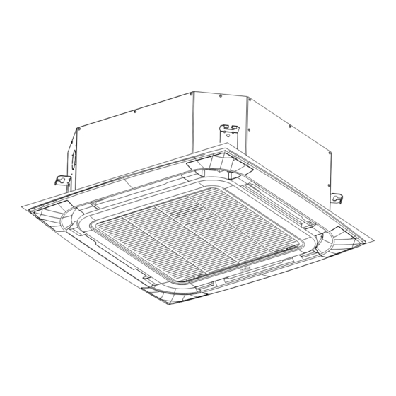
Page 12: Installation Of Panel
INSTALLATION OF PANEL ¾ Å ³ ö · ç Ã æ ° å µ Ä ° ² × ° ¾ Å ³ ö · ç Ã æ ° å µ Ä ° ² × ° BODY DIMENSION: Unload air-in grille Take off air-in grille Unload panel installation cap INSTALLATION OF PANEL... -
Page 13: Outdoor Unit Installation
OUTDOOR UNIT INSTALLATION Location for installing outdoor unit 1. Install it at a place where it is convenient for installation and well ventilated. 2. Keep the required distance away from the wall as reqiured on the previous page when carrying on installation. 3. -
Page 14: Refrigerant Pipe Installation
REFRIGERANT PIPE INSTALLATION CAUTION Ventilate the air if there was any refrigerant leakage during the installation. Leaked refrigerant will generate poisonous gas if meeting fire. Make sure there is no refrigerant leakage after the installation. Leaked refrigerant will generate poisonous gas if meeting fire. Allowed Length and Drop of Pipes Requirements are different when installing the outdoor unit. -
Page 15: Air Purging
The following figure only shows the assembly relationship of the indoor unit ,outdoor unit and refrigerant pipes. Please refer to the following figures to install. NOTE The throttle subassembly has been installed in the outdoor unit.. Use two spanners to connect the pipe with indoor/outdoor pipes to avoid the copper pipe cracking. Please pay attention to the connection orientation when connecting. -
Page 16: Charge Additional Refrigerant
indoor unit 3-way valve diagram refrigerantflow direction Connect to indoor unit 3-way valve Close position Connect to outdoor unit Valve spindle Exhaust mouth Exhaust nut Valve core Exhaust spindle outlet nut additional freon refrigerant pot Connect hose Air exhaust process: (6). -
Page 17: Electric Wiring
Specification of Max. length R410A Liquid pipe 6.35 (L-5)X0.022 kg (L-5)X0.03kg 9.52 (L-5)X0.054kg (L-5)X0.05kg 12.7 (L-5)X0.11kg (L-5)X0.10kg (* "L" refers to length of connection pipe.) The additional refrigerant should be charged from the service port of the 3-way valve when the appliance is operating in cooling mode. Do not allow air enter the refrigeration system while charging refrigerant. - Page 18 CAUTION Power cord is to be selected according to national regulations. Outdoor unit power cord should be selected and connected according to the outdoor unit installation manual. Wiring should be away from high temperature components, or the insulation layer of the wires may melt down.
-
Page 19: Test Run
3. External wiring diagrams Electric heater Power supply cord Power supply circuit breaker (prepared by user) Power supply Power supply circuit breaker(prepared by user) Power supply Defrost connecting cable Control connecting cable Outdoor Indoor unit unit Power supply connecting cable Power supply cord TEST RUN Before testing... -
Page 20: Adjusting Air Flow Direction
ADJUSTING AIR FLOW DIRECTION Cassette Type While the unit is in operation, you can adjust the air flow louver to change the flow direction an ralize the room temperature evenly. Thus you can enjoy it more comfortably. 1.Set the desired air flow direction. Push the SWING button to adjust the louver to the desired position and push this button aga maintain the louver at this position. - Page 21 Checks before operation CAUTIONS Check that the wiring is not broken off or disconnected. Check that the air filter is installed.(Some air-conditioners have no air filters) Check that the outdoor unit air outlet or inlet is not blocked. Before you clean the air conditioner, be sure to disconnect the power supply plug. Clean the air filter The air filter can prevent the dust or other particulate from going inside.In case of blockage of the filter,the working efficiency of the air conditioner may greatly decrease.
-
Page 22: Important Safety Information
IMPORTANT SAFETY INFORMATION CAUTION Do not attempt to install this unit by yourself.This unit requires installation by qualified persons. DANGER Do not attempt to service the unit yourself.This unit has no user serviceable components.Opening or removing the cover will expose you to dangerous voltage.Turn off the power supply will not prevent potential electric shock. -
Page 23: Troubles And Causes
These are not failures Room air is smelly. A bad odor comes from the air conditioner. Smells impregnated in the wall,carpet,furniture,clothing,or furs,are coming out. A white mist of chilled air or water is generated from the outdoor unit. CAUTION If any of the following conditions occur,stop the air conditioner immediately,set off the power switch, and contact the dealer. - Page 24 Error code Fault code of indoor unit Error Code Failure Failure description Remarks Indoor ambient sensor fault 1 Check whether the sensors are normal. Indoor coil sensor fault 2 Check whether the sensors are Outdoor coil sensor Connected. Faultsensor fault (if there is an outdoor control board) 1.View the fault code of outdoor unit.
- Page 25 Fault code of outdoor unit Lighting Flashing(1Hz) Extinguishing Solutions Priority Gree Blue Faults/States Phase-sequence error 1.Check whether the Power phase is normal. Phase-loss 1.Check whether the high High pressure protection pressure is normal. 1.Check whether the exhaust Exhaust temperature protection temperature is normal.
-
Page 26: Remote Controller
WIRING DIAGRAM REMOTE CONTROLLER Button Function (TEMP UP) Increase the temperature or time by 1 unit (TEMP DN) Decrease the temperature or time by 1 unit ON/OFF To switch the conditioner on and off. In cooling mode,press this button ,the temperature will increase 2 on the base of setting temperature In heating mode, press this button, the temperature... - Page 27 Remote control DISPLAY Meaning of symbols on the liquid crystal display Meaning No. Symbols FEEL mode indicator COOLING indicator DEHUMIDIFYING indicator FAN ONLY OPERATION indicator HEATING indicator TIMER OFF indicator TIMER ON indicator AUTO FAN indicator LOW FAN SPEED indicator MIDDLE FAN SPEED indicator HIGH FAN SPEED indicator SLEEP indicator...
- Page 28 COOLING MODE The cooling function allows the air conditioner to cool the room and at the same time reduces the humidity in the air. To activate the cooling function ( COOL ) , press the MODE button until the symbol appears on the display.
- Page 29 TIMER MODE----TIMER ON To set the automatic switching on of the air conditioner. To program the time start,the appliance should be off. Press TIMER , Set the temperature with pressing the key ,Press TIMER Again , set the time with pressing the key , Press the key more times till on the display you can read the time which passes between the programming and the timed start.
- Page 30 FEEL MODE To activate the FEEL (automatic) mode of operation, press the MODE button on the remote control until the symbol appears in the display. In the FEEL mode the fan speed and the temperature are set automatically according to the room temperature (tested by the probe which is incorporated in the indoor unit)to ensure user comfort.
- Page 31 Remote controller handling procedure Batteries replacing procedure Following cases signify dead cells.Replace the dead batteries with new ones. Following cases signify dead cells.Replace the dead batteries with new ones. Receiving sound is not emitted from the unit when signal is transmitted. Receiving sound is not emitted from the unit when signal is transmitted.
- Page 32 Air flow direction adjustment procedure Adjusting air flow direction Up/down direction can be adjusted by using the AIRFLOW button on the remote controller. Up/down direction can be adjusted by using the AIRFLOW button on the remote controller. This button,each time pressed,changes the mode in the following sequence: This button,each time pressed,changes the mode in the following sequence: AUTO push the LOUVER button,changes the mode to swing louver .
Need help?
Do you have a question about the OSH-T18HRK3 and is the answer not in the manual?
Questions and answers