
Related Manuals for DÖRR EcoPump HP


Summary of Contents for DÖRR EcoPump HP
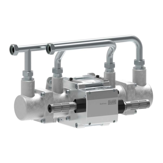
- Page 1 EcoPump HP Pneumatic Horizontal Piston Pump Operation manual MPU00020EN, V01 N24160008, N24160009, N24160010 www.durr.com...
- Page 2 Illustrations can deviate from the technical con- struction. Validity range of the document This document describes the following product: N24160008 EcoPump HP 400 21 N24160009 EcoPump HP 800 21 N24160010 EcoPump HP 1600 21 Applicable documents If you use accessories, follow the operating instruc- tions for the accessories.
-
Page 3: Table Of Contents
9.1 Safety notes........... 15 12.11 Material specification......39 9.2 General notes......... 16 Replacement parts, tools and accesso- 9.3 Maintenance schedule......16 ries..............40 9.4 Dismantle and assemble control unit..17 13.1 Replacement parts....... 40 08/2020 EcoPump HP - MPU00020EN 3/56... - Page 4 13.1.1 Control Unit........40 13.1.2 Fluid part........... 42 13.1.3 Motor..........45 13.1.4 Manifolds........... 48 13.1.5 Repair kits......... 48 13.1.6 Seal sets..........49 13.2 Tools............. 49 13.3 Accessories.......... 49 13.4 Order............ 50 Index.............. 51 4/56 EcoPump HP - MPU00020EN 08/2020...
-
Page 5: Product Overview
The EcoPump HP is an auto-suction pneumatic hori- zontal piston pump. 2 Hose leakage indicator 3 Fluid parts The EcoPump HP may only be used for pumping water-based and solvent-based flammable and non- 4 Sound muffler flammable coating materials and their detergents. -
Page 6: Residual Risks
Guidelines, Standards and Rules of Engineering installed, from compressed air and material supply. Local conditions Depressurize the lines. Electrical Systems and Their Loading Limits Secure the system against being switched on again. Technical Measures for occupational safety and health 6/56 EcoPump HP - MPU00020EN 08/2020... -
Page 7: Personal Protective Equipment
Thermal forces Chemical effects Protective workwear Tight fitting workwear with low tear strength, tight sleeves and no hanging parts. Respirator mask Protects from hazardous gases, vapors, dust and similar materials and media. 08/2020 EcoPump HP - MPU00020EN 7/56... -
Page 8: Motor
Serious injury and death could be the consequence. Unpack product outside Ex zones. Discharge the product. Dispose packaging outside of the Ex zone in accordance with the regulation or store properly for a later return. 8/56 EcoPump HP - MPU00020EN 08/2020... -
Page 9: Transport
Lift heavy loads only by using suitable hoists. Protective equipment: Protective gloves Protective workwear Anti-Static Safety Boots 1. Check the pump for integrity on receiving it. 2. Report defects immediately Ä “Hotline and Con- tact”. 08/2020 EcoPump HP - MPU00020EN 9/56... -
Page 10: Requirements For The Installation Point
Mount pump 4. Secure insertion nipple (4) using the threaded pin such that connections (1) and (2) point upwards. (5). The threaded pin is included in the scope of supply of EcoPUC A. 10/56 EcoPump HP - MPU00020EN 08/2020... -
Page 11: Connecting
Movement of the piston and of the flowing material create the charge. The charge can only flow if the piston pump is grounded with all components. Con- nection of the suction pipe and pressure pipe are not sufficient for grounding. 08/2020 EcoPump HP - MPU00020EN 11/56... -
Page 12: Commissioning
For work within the Ex zone, use tools with the corresponding Ex labeling. The operator must ensure that connected pipe- lines or hose lines are tested according to the specifications in force (e.g. pressure test). 12/56 EcoPump HP - MPU00020EN 08/2020... -
Page 13: Setting Operating Parameters
6bar connection air pressure. If the pump is not in operating mode, the number of cycle of the pump can drop down to the minimum flow velocity of the medium. This reduces pump wear and operating costs. 08/2020 EcoPump HP - MPU00020EN 13/56... -
Page 14: Cleaning
Do not use abrasive cleaning tools. tion. Do not use compressed air for cleaning. Do not use any thinner spray guns. Do not use high pressure for cleaning agents. 14/56 EcoPump HP - MPU00020EN 08/2020... -
Page 15: Cleaning
Disconnect the system with the product from For work within the Ex zone, use tools with the power supply and material supply. corresponding Ex labeling. Secure the system against being switched on again. Depressurize the lines. 08/2020 EcoPump HP - MPU00020EN 15/56... -
Page 16: General Notes
Replace valve in the control unit. Ä 9.4.3 “Removing the valve” Replace non-return valves Ä 9.5.3 “Dismantling non-return every 5 years valve in the outlet cylinder”, Ä 9.5.5 “Dismantle non-return valve in the piston”. 16/56 EcoPump HP - MPU00020EN 08/2020... -
Page 17: Dismantle And Assemble Control Unit
2. Remove control unit (2) from the motor. 3. Remove O-rings between control unit and motor. 9.4.2 Remove membrane Fig. 12: Remove membrane Personnel: Mechanic + additional qualification explosion protection + Additional qualification high pressure 08/2020 EcoPump HP - MPU00020EN 17/56... -
Page 18: Removing The Valve
(5). ð If the piston works properly and the control unit is leaking, the O-rings on the valve could be damaged. 5. Check O-rings on the valve for damage. ð Replace damaged O-rings. 18/56 EcoPump HP - MPU00020EN 08/2020... -
Page 19: Assembling Valve
4. Firmly attach control unit (2) with four screws (1). ð Respect tightening torque. 3. Grease valve (3). 4. Carefully push the valve (3) into the distributor block using a suitable tool (e.g. W02850031). 5. Place spacer (2) on the valve. 08/2020 EcoPump HP - MPU00020EN 19/56... -
Page 20: Dismantling And Assembling Fluid Parts
2. Tighten four screws (1). Respect tightening torque. Personnel: Mechanic + additional qualification explosion protection Protective equipment: Protective gloves Protective workwear Anti-Static Safety Boots 1. Remove four screws (1). 2. Pull out housing (2) carefully from the piston (3). 20/56 EcoPump HP - MPU00020EN 08/2020... -
Page 21: Dismantling Non-Return Valve In The Outlet Cylinder
5. Insert the valve ball guide (3) into the outlet cyl- inder housing (7). 6. Place sealing ring (2) in outlet cylinder housing (7). 7. Thread-in the screw-in socket (1) in outlet cylinder housing (7). 08/2020 EcoPump HP - MPU00020EN 21/56... -
Page 22: Dismantle Non-Return Valve In The Piston
4. Remove gasket (3). 5. Remove O-Ring (2). 9.5.6 Assemble non-return valve in the piston Fig. 22: Assemble non-return valve in the piston N24160008: 2Nm N24160009, N24160010: 6Nm Klüber Syntheso GLEP 1 Loctite 222 22/56 EcoPump HP - MPU00020EN 08/2020... -
Page 23: Dismantling Inlet Cylinder
4. Carefully slide intake cylinder housing (4) over the bellows (2). 5. Secure intake cylinder housing (4) with four greased screws (8). Do not tighten screws (8) yet. 6. Slide piston (5) onto the piston rod (1). 08/2020 EcoPump HP - MPU00020EN 23/56... -
Page 24: Dismantle And Assemble Motor
2. Pull out seal housing (2) with piston guide belt (1), O-ring (3) and rod seal (4) from the piston rod (5). 3. Loosen and remove four screws (6) on one side of the motor. 4. Remove front plate (9) from the tube (8). 24/56 EcoPump HP - MPU00020EN 08/2020... -
Page 25: Assemble Motor
Fig. 28: Assemble piston rod and piston guide band (6) onto the piston rod (10). Klüber Syntheso GLEP 1 9. Assemble leakage indicator hose (12). Lubricant for piston (included in the scope of supply) 08/2020 EcoPump HP - MPU00020EN 25/56... -
Page 26: Faults
Replace piston seal of the motor. Piston seal of the motor defective Check seals and pipe connections. Pump does not pump. There is air in the suction line. Check material supply line. Vent the system. 26/56 EcoPump HP - MPU00020EN 08/2020... - Page 27 Air enters the slurry circuit. bore Replace bellows Ä 9.5.7 “Dismantling inlet cyl- Paint leak from the Bellows defective inder”. leakage bore If in contact with solvent, replace rod seal of the air motor as well. 08/2020 EcoPump HP - MPU00020EN 27/56...
-
Page 28: Troubleshooting
ATEX guidelines can cause explosions in an explosive atmosphere. Serious injury and death could be the consequence. Use exclusively original replacement parts. There is one changeover valve each on both sides of the motor. 28/56 EcoPump HP - MPU00020EN 08/2020... -
Page 29: Assembling Ice Reduction
(2). 10.2.2 Assembling ice reduction 10.2.2.1 EcoPump HP 400 and EcoPump HP 800 If the noise mufflers are frosted from inside during the operation of the pump, it is advisable Fig. 32: Ice reduction kit to install the “frost-reducing” accessory Ä 10.1 “Defects table”. - Page 30 Fig. 34: Throttle valve 6. Screw the reducing nipple (9) into the throttle valve (8) hand-tight. 7. Screw in the throttle valve (8), reducing nipple (9) and sealing washer (10) in switch-over on the con- trol unit. 30/56 EcoPump HP - MPU00020EN 08/2020...
- Page 31 1. Remove the pneumatic connection (4) from the control unit (3). 2. Remove two silencers (1) and two adapters (2) Fig. 37: Adjust throttle from the control unit (3). 1. Turn throttle valve (1) clockwise. 08/2020 EcoPump HP - MPU00020EN 31/56...
- Page 32 Fig. 40: Connect adapter with throttle valve 6. Screw the throttle valve (10) into the connection block (11). 7. Close the opposite side with the plug (12). 8. Screw the connection block (11) into the control unit (3). 32/56 EcoPump HP - MPU00020EN 08/2020...
-
Page 33: Disassembly And Disposal
Secure the system against being switched on again. Depressurize the lines. Ensure that the pump is unpressurized. Install appropriate pressure release device, e.g. valve or ball valve, to ensure safe depressuriza- tion. 08/2020 EcoPump HP - MPU00020EN 33/56... -
Page 34: Disassembly
Ex zones. It can cause serious injuries or death. If possible, carry out cleaning and maintenance work outside the Ex zones. For work within the Ex zone, use tools with the corresponding Ex labeling. 34/56 EcoPump HP - MPU00020EN 08/2020... -
Page 35: Disposal
5. Disassemble pump from the wall or the device. 2. Remove the seals. Ensure professional disposal. 6. Lay down or store the pump as specified. 3. Dispose of individual parts of the pump professio- nally. 08/2020 EcoPump HP - MPU00020EN 35/56... -
Page 36: Technical Data
10°C Media temperature, max. 50 °C Fig. 45: Dimensions N24160009 Ambient temperature, min. 15°C Ambient temperature, max. 40°C N24160009 Value Relative humidity, min. Height 371.5mm Relative humidity, max. Width 635.6mm Depth 274mm Weight 56kg 36/56 EcoPump HP - MPU00020EN 08/2020... -
Page 37: Emissions
Compatible with the materials used Ä 12.11 “Mate- Permissible air pressure, max. 6 bar rial specification” 12.6 Compressed air quality The quality of the compressed air complies with ISO 8573-1:2010 class 1:4 (≤ -3 °C):1 08/2020 EcoPump HP - MPU00020EN 37/56... -
Page 38: Characteristic Curve Of The Outflow Rate
Fig. 47: Characteristic curve N24160001, N24160008 Medium [bar (psi)] Pump head [1/min] Number of cycles [l/min (gal/min)] Volume flow Fig. 48: Characteristic curve N24160002, N24160009 Medium [bar (psi)] Pump head [1/min] Number of cycles [l/min (gal/min)] Volume flow 38/56 EcoPump HP - MPU00020EN 08/2020... -
Page 39: Material Specification
[l/min (gal/min)] Volume flow 12.11 Material specification Requirements for delivered media Detail Value Viscosity, min. 40mPa s Viscosity, max. 250mPa s Diameter of the solids contained, 400μm max. Fig. 49: Characteristic curve N24160003, N24160010 Conductivity, min. 1000pS/m 08/2020 EcoPump HP - MPU00020EN 39/56... -
Page 40: Replacement Parts, Tools And Accessories
Replacement parts, tools and accessories Replacement parts, tools and accessories 13.1 Replacement parts 13.1.1 Control Unit Fig. 50: Control unit replacement parts 40/56 EcoPump HP - MPU00020EN 08/2020... - Page 41 Screw-in plug connector D22 G3/4" O-ring 27x2 Included in Kit N24960084 O-ring 46x3 Included in Kit N24960083 O-ring 6x2 Included in Kit N24960084 O-ring 25x1.4 Included in Kit N24960084 Cylinder screw M8x55 Locking screw G1/2'' 08/2020 EcoPump HP - MPU00020EN 41/56...
-
Page 42: Fluid Part
Replacement parts, tools and accessories 13.1.2 Fluid part Fig. 51: Fluid part spare parts 42/56 EcoPump HP - MPU00020EN 08/2020... - Page 43 Intake cylinder housing Outlet cylinder housing Screw-in socket DN25 G1” Screw-in socket DN25 G1 1/2” M59040042, contained in Bellows D25 N24960182 Piston Valve ball guide Guide valve ball pressure side G1 1/2'' Compression spring fix bracket 08/2020 EcoPump HP - MPU00020EN 43/56...
- Page 44 Contained in N24960180 Sealing ring D43.5 Contained in N24960180 Clamping ring Ball D44.45 Contained in N24960180 Ball D31.75 Contained in N24960180 Compression spring O-Ring 50x1.5 Contained in N24960180 O-Ring 41x1.78 Contained in N24960180 O-Ring DN25 44/56 EcoPump HP - MPU00020EN 08/2020...
-
Page 45: Motor
Replacement parts, tools and accessories Position Denomination Quantity Repair set, seal set Cylinder screw M12x40 with Safety washer Cylinder screw M6x16 Cylinder screw M6x25 13.1.3 Motor Fig. 52: Motor Replacement Parts 08/2020 EcoPump HP - MPU00020EN 45/56... - Page 46 Bracket for pump Piston seal D180 Contained in N24960183 Piston guide belt O-ring 180x3 Contained in N24960183 O-ring 42x1.5 Cylinder screws M12x40 Cylinder screws M12x25 Safety washer Locking screw G1/8" Elbow plug-in connection G1/8" Retainer ring 46/56 EcoPump HP - MPU00020EN 08/2020...
- Page 47 Contained in N24960176 Piston guide belt O-Ring 260x3 Contained in N24960176 O-ring 42x1.5 Cylinder screws M12x40 Cylinder screws M12x25 Safety washer Locking screw G1/8" Elbow plug-in connection G1/8" Retainer ring Cylinder screws M6x55 Hose leakage indicator 08/2020 EcoPump HP - MPU00020EN 47/56...
-
Page 48: Manifolds
Gasket D64 N24960181 for N24160008 Gasket D44.5 Determination Quantity Sealing ring D43.5 Gasket D44.5 Ball D44.45 Gasket D30.2 Ball D31.75 Sealing ring D29 O-Ring 50x1.5 Ball D31.75 O-Ring 41x1.78 Ball D19.05 O-Ring 35x1.5 O-ring 25x2.5 48/56 EcoPump HP - MPU00020EN 08/2020... -
Page 49: Seal Sets
N24960175 for N24160008 EcoTube DN25 on G3/4" M81120016 Quan- Determination tity Valve for dry run protection Piston seal DN65 Material Denomination number N24960179 for N24160009 3/2 valve pneumatic M54410033 Quan- Determination tity Piston seal DN95 08/2020 EcoPump HP - MPU00020EN 49/56... -
Page 50: Order
EcoPUC A F30300001 EcoPUC A RA F30300002 EcoPUC A RA BUS F30300003 Ice reducing Material Designation number Ice reduction kit for EcoPump HP N24970033 400 / 800 Ice reduction kit for EcoPump HP N24970019 1600 50/56 EcoPump HP - MPU00020EN 08/2020... -
Page 51: Index
Humidity ....... . . 36 08/2020 EcoPump HP - MPU00020EN 51/56... - Page 52 Operating temperature ..... . 36 EcoPump HP 400 ..... . . 29 Operation EcoPump HP 800 .
- Page 53 Year of manufacture ......37 Technical data Compressed air quality ....37 08/2020 EcoPump HP - MPU00020EN 53/56...
- Page 54 54/56 EcoPump HP - MPU00020EN 08/2020...
- Page 55 08/2020 EcoPump HP - MPU00020EN 55/56...
- Page 56 Dürr Systems AG Application Technology Carl-Benz-Str. 34 74321 Bietigheim-Bissingen Germany Phone +49 7142 78-0 www.durr.com Translation of the original operation manual MPU00020EN, V01 Transmission and duplication of this document, as well as use and sharing of its contents are not per- mitted without express written approval.
Need help?
Do you have a question about the EcoPump HP and is the answer not in the manual?
Questions and answers