Table of Contents
Advertisement
Quick Links
Advertisement
Table of Contents

Subscribe to Our Youtube Channel
Related Manuals for DÖRR EcoPump VP 55 200 DE


Summary of Contents for DÖRR EcoPump VP 55 200 DE
- Page 1 EcoPump VP Package Operation manual MPU00016EN, V06 www.durr.com N92110001V...
- Page 2 Dürr Systems AG Application Technology Carl-Benz-Str. 34 74321 Bietigheim-Bissingen Germany Phone +49 7142 78-0 Internet: www.durr.com Translation of the original operation manual MPU00016EN, V06 The reproduction and distribution of this document, use and communication of its contents are not permitted without express written approval.
- Page 3 Information about the document This document describes the correct handling of the product. Read the document prior to every activity. Prepare the document for the application. Pass on the product only together with the com- plete documentation. Always follow safety instructions, handling instructions and specifications of every kind.
-
Page 4: Table Of Contents
TABLE OF CONTENTS Maintenance..........23 Product overview........5 9.1 Safety notes........23 9.2 Maintenance schedule...... 24 1.1 Overview..........5 9.3 Maintenance work......25 1.2 Short description......... 5 9.3.1 Fill the oiler........25 Safety............5 9.3.2 Lubrication........25 2.1 Presentation of Notes......5 9.3.3 Replace filter of the maintenance 2.2 Intended Use........ -
Page 5: Product Overview
Product overview Product overview Safety Overview Presentation of Notes The following notes can appear in this instruction: DANGER! High risk situation that can lead to serious inju- ries or death. WARNING! Medium risk situation that can lead to serious injuries or death. CAUTION! Low risk situations that can lead to minor injuries. -
Page 6: Residual Risks
Safety Misuse Danger from harmful or irritant substances Not using as intended entails danger to life. Serious injuries or death can result if you come into contact with dangerous fluids or steam. Examples of wrong use are: System Check regularly for leakage. Observe Installation of the system in an areas without local regulations and maintenance schedule. -
Page 7: Conduct In The Event Of A Hazardous Situation
Safety Furthermore, he has the following knowledge: Sparks due to electrostatic discharge Guidelines, Standards and Rules of Engi- If the system is not properly grounded or the neering potential equalization fails, components may get Local conditions charged electrostatically. Electrostatic discharge can cause sparks that in explosive atmosphere Technical Measures for occupational safety and can cause a fire or an explosion. -
Page 8: Design And Function
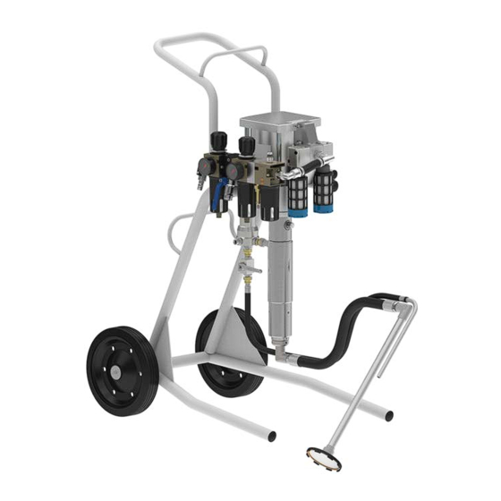
Depending on the requirement, the system can be fitted with a suitable pump. Systems are available in various versions: Denomination Material number EcoPump VP 55 200 DE N24170005 EcoPump VP 55 310 DE N24170006 EcoPump VP 55 445 DE N24170007 Fig. -
Page 9: Pneumatic Maintenance Unit For Com- Pressed Air Preparation
Design and Function Pneumatic maintenance unit for com- pressed air preparation Fig. 4: Maintenance unit 1 FRL 3/8'' 2 FRL 1/4'' Fig. 5: Maintenance unit 3 FRLP 1/2'' - 07 1 Regulator 4 DFRL 3/8'' 2 Pump connection 5 DFRL 1/4'' 3 Pressure gage 6 DFRLP 1/2'' –... -
Page 10: Suction Module
Design and Function Suction module When using the feed cup, remember the following: Operate feed cup only with lid (1). Open the lid (1) (e.g. for topping up) only if the system is depressurized. Do not open during operation or during purging. Do not circulate fluids. -
Page 11: Transportation Module
Transport, scope of supply and storage The pump can be easily transported using the Transport carriage (1). The rollers of the trolley (1) are dissipative. The mobile stand (2) has a firm stand during application. Wheels are relieved. The rollers of the mobile stand (2) are dissipative. -
Page 12: Transport
Assembly Transport Assembly Assembling wall mount NOTICE! Assemble the system under the following Incorrect Transport conditions: Improper transportation of the system may cause – Work in pairs when assembling the the agitator the systemto fall and suffer damage. system. – Protect System from moisture. –... -
Page 13: Connecting
Assembly Connecting Connect paint hose Personnel: Mechanic + additional qualification explosion protection + Additional qualification high pressure Protective equipment: Protective gloves Protective workwear Anti-Static Safety Boots With ball valve Fig. 13: Connect paint hose to the filter 1. Screw ball valve with manifold (1) to the lateral connection of the filter (2). -
Page 14: Assembling Ground Conductor
Commissioning Compressed air supply If the compressed air supply is not suffi- ciently dimensioned, the optimum pump power may not be reached. Fig. 15: Connecting Ground 1. Remove grounding screw (2) from the grounding hole on the motor (1). 2. Remove lock washer (3). Leave washer (4) in the groove. -
Page 15: Commissioning
Commissioning Requirements: WARNING! System is assembled Ä 5 “Assembly”. Excessive input pressure System is grounded Ä 5.4 “Assembling ground conductor”. Charging the pump with excessive input pressure There is still some test medium in the pump. will damage the pump. Serious injuries and death can be the consequence. -
Page 16: Operation
Operation 12. Close ball valve (1) on the depressurization module. ð The pump stops. 13. Unlock application device (e.g. spray gun). Align with the tip on the container wall of the collecting tray. 14. Open application device. ð The pump starts. 15. -
Page 17: General Notes
Operation WARNING! NOTICE! Danger due to squirting material Dried material residues This can cause serious injuries. If material residues dry in the system, that can harm components. – Use only spray guns designed for the max- imum pressure of the pump. –... -
Page 18: Switching On
Operation Switching on 3. Open ball valve of the compressed air supply. There may be material pressure after the purge. Personnel: Mechanic + additional qualification explosion protection + Additional qualification high pressure Protective equipment: Protective gloves Protective workwear Anti-Static Safety Boots Face protection Requirements: Compressed air supply is switched on Ä... -
Page 19: Switching Off
Operation 9. Close ball valve (1) on the depressurization 1. Close and lock application device. module. ð The pump stops. ð The pump stops. 2. Purge the system Ä 7.5 “Rinsing”. 10. Unlock application device (e.g. spray gun). 3. Ensure that the ball valve on the compressed Align with the tip on the container wall of the air supply is closed. -
Page 20: Rinsing
Operation Rinsing Purge and clean system after end of work every time. It is advisable to create a purging program and cleaning program in relation to the coating material used, to ensure reliable functioning of the system. Personnel: Mechanic Fig. 23: Lock maintenance unit + additional qualification explosion protection 1. -
Page 21: Cleaning
Cleaning 8. If applicable, Place recirculation (4) in a col- lector tray. Secure against falling out. Cleaning When using flammable media, ensure that a Safety recommendations suitable potential equalization line is clamped to the collector vessel. WARNING! 9. Open ball valve (2) of the pneumatic mainte- nance unit. -
Page 22: Cleaning
Cleaning WARNING! WARNING! Material escaping under pressure Damage to hearing due to escaping com- pressed air Material leaking under high pressure can pene- trate the body. Even if the injury looks like a Setting the nozzle incorrectly on the nozzle harmless cut wound, the penetrating material cleaner will allow compressed air to escape. -
Page 23: Maintenance
Maintenance WARNING! Danger due to freezing The noise mufflers on the motor can cool down drastically. Contact with it can result in frostbite. – Before working on the motor, ensure that the noise muffler is at room temperature. WARNING! Material escaping under pressure Material leaking under high pressure can pene- trate the body. -
Page 24: Maintenance Schedule
Maintenance Maintenance schedule If a maintenance assistant is used in the system visualizer, the maintenance intervals of the mainte- nance assistant are valid. The maintenance intervals given below are based on experiential values. Adapt the maintenance intervals to suit requirements. Interval Maintenance work Check the system for damage and leakages. -
Page 25: Maintenance Work
Maintenance Maintenance work Anti-Static Safety Boots 9.3.1 Fill the oiler Requirements: System is switched off Ä 7.4 “Switching off”. Fig. 27: Oiler maintenance unit The pump can be lubricated automatically through Fig. 28: Maintenance unit of oiler the maintenance unit. The oiler (1) is now filled with oil. -
Page 26: Replace Filter Of The Maintenance Unit
Maintenance 9.3.3 Replace filter of the maintenance unit. 9.3.4 Replacing filter disk Personnel: Mechanic + additional qualification explosion protection + Additional qualification high pressure Protective equipment: Protective workwear Protective gloves Anti-Static Safety Boots Eye protection Requirements: System is switched off Ä 7.4 “Switching off”. Fig. -
Page 27: Replace Filter Cartridge
Maintenance 9.3.5 Replace filter cartridge Dismantle and assemble 9.4.1 Dismantling Personnel: Mechanic + additional qualification explosion protection + Additional qualification high pressure Protective equipment: Anti-Static Safety Boots Eye protection Protective workwear Protective gloves Requirements: System is purged Ä 7.5 “Rinsing”. System is switched off Ä... - Page 28 Maintenance Disassembling ball valve Fig. 33: Disassemble compressed air hose Fig. 35: Disassembling ball valve 3. Disassemble compressed air hose on the pump (1) using a hexagon spanner. 7. Disconnect screw connection (1). 8. Remove ball valve from filter. Disassemble filter Fig.
-
Page 29: Assembly
Maintenance 9.4.2 Assembly 10. Remove filter from the pump. Disassemble suction module CAUTION! 11. Unscrew suction module from the pump using Risk of injury due to screw connections dis- a hook spanner Ä 13.2 “Tools”. engaging themselves Disassemble pump Bolted connections could loosen up if there are vibrations. - Page 30 Maintenance Assemble pump Assembling Filter Fig. 39: Assembling Filter 5. Screw filter to the material outlet of the pump Fig. 38: Assemble pump (1). Observe tightening torque. Assemble suction module Work in pairs when lifting the pump. Insert pump into the transportation module from above.
-
Page 31: Faults
Faults 6. Push suction module (3) into the pump (1) from 11. Secure maintenance unit against toppling. below. 12. Attach maintenance unit with screws (1) to the 7. Insert hook spanner in hole (2). Screw on suc- angle bracket of the transportation module. tion module (3). -
Page 32: Defects Table
Disassembly and Disposal 10.2 Defects table Fault description Cause Remedy Pump pressure and material pressure Filter soiled Replace filter Ä 9.4 “Dismantle and assemble”. are too low. Check setting of the pneumatic Pneumatic maintenance maintenance unit. unit is incorrectly set. Check air hose. -
Page 33: Disassembly
Technical data 11.2 Disassembly Transport trolley Personnel: Mechanic + additional qualification explosion protection + Additional qualification high pressure Protective equipment: Eye protection Protective gloves Anti-Static Safety Boots Protective workwear Requirements: System is purged Ä 7.5 “Rinsing”. System is depressurized Ä 7.4 “Switching off”. Compressed air supply is switched off. -
Page 34: Connections
Technical data 12.4 Emissions Wall mount Detail Value Sound pressure level <80dB(A) 12.5 Operating values The performance data depend on the pump used. See operating instructions for the pump Ä “Applicable documents”. 12.6 Compressed air quality Purity classes following ISO 8573-1::2010 1:3:1 1:4:1 Limitations for purity class 4 (pressure dew point max.):... -
Page 35: Operating And Auxiliary Materials
Replacement parts, tools and accessories 12.8 Operating and auxiliary materials Replacement parts, tools Cleaning agents and accessories Cleaning agents must meet the following require- ments: 13.1 Spare part Suitable for use in explosive areas. Filter insert for suction modules Compatible with the materials used Value Material number Detergent... - Page 36 Replacement parts, tools and accessories Pressure gage for maintenance unit Ball valve for pressure release Description Material number Description Material number Pump air max. 8bar W07010347 Ball valve with manifold M54300607 Pump air max. 7bar W07010346 Ball valve M54300608 Atomizer air max. 3bar W07010345 Nozzle cleaning Maintenance units...
-
Page 37: Tools
Replacement parts, tools and accessories Operating materials Item Denomination Material number Description Material number Suction lance 950mm M34010517 Oil Nuto H 32 0.2L as W32020048 release agent Suction lance 950mm M34010516 with filter Oil Nuto H 32 1.0L as W32020049 release agent Suction lance 500mm M34010515... -
Page 38: Order
Replacement parts, tools and accessories Description Material number Swivel joint M22150012 Connection set applicator N92960002 500bar 13.4 Order WARNING! Risk of injury from unsuitable replacement parts in explosive areas. Replacement parts not compliant with the speci- fications of the ATEX guidelines can cause explosions in an explosive atmosphere. -
Page 39: Index
14 INDEX Accessories ......37 Fault Advanced training ......7 Behavior in the event of faults . - Page 40 Output pressure ......34 Replace filter disk ..... 26 Overview .
- Page 41 12/2019 EcoPump VP Package - MPU00016EN 41/44...
- Page 42 42/44 EcoPump VP Package - MPU00016EN 12/2019...
- Page 43 12/2019 EcoPump VP Package - MPU00016EN 43/44...
- Page 44 Dürr Systems AG Application Technology Carl-Benz-Str. 34 74321 Bietigheim-Bissingen Germany www.durr.com Phone +49 7142 78-0 Translation of the original operation manual The reproduction and distribution of this document, use and communication of its contents are not permitted without express written approval. Offenders will be liable for damages. All rights in the event of a patent grant or design regis- tration are reserved.
Need help?
Do you have a question about the EcoPump VP 55 200 DE and is the answer not in the manual?
Questions and answers