Advertisement
Quick Links
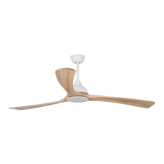
Norfolk Aero DC Smart Series Installation Guide
Thanks for choosing our Norfolk Aero DC Smart Series ceiling fan.
We strongly recommend that you read this manual carefully before installation.
Models Parameters (Fan Only):
MNDC183WN
1765mm 3 Blade DC WiFi Ceiling Fan Matt White/Natural
MNDC183WW
1765mm 3 Blade DC WiFi Ceiling Fan Matt White/Whitewash
MNDC183MW
1765mm 3 Blade DC WiFi Ceiling Fan Matt Black/Walnut
MNDC223WN
2175mm 3 Blade DC WiFi Ceiling Fan Matt White/Natural
MNDC223WW
2175mm 3 Blade DC WiFi Ceiling Fan Matt White/Whitewash
MNDC223MW
2175mm 3 Blade DC WiFi Ceiling Fan Matt Black/Walnut
Part List:
Qty 1 x Motor assembly
Qty 1 x Mounting bracket
Qty 1 x Downrod
E: sales@martecltd.com.au IP: 02 8778 7500
www.martecaustralia.com.au
Qty 1x Instruction manual
Qty 1 x Remote & Receiver
Qty 1 x
Canopy
Qty 1x Coupling cover
Qty 1 x Screw kit
Qty 1x Decorative ring
Qty 3x Blades
Qty 1xBlade fixing metal plate
Qty 1x Bottom plate
Advertisement

Related Manuals for Martec Norfolk Aero DC Smart Series


Summary of Contents for Martec Norfolk Aero DC Smart Series
- Page 1 Norfolk Aero DC Smart Series Installation Guide Thanks for choosing our Norfolk Aero DC Smart Series ceiling fan. We strongly recommend that you read this manual carefully before installation. Models Parameters (Fan Only): MNDC183WN 1765mm 3 Blade DC WiFi Ceiling Fan Matt White/Natural...
-
Page 2: Important Safeguards
WARNING IMPORTANT SAFEGUARDS: Means for disconnection must be incorporated in the fixed wiring in accordance with the wiring rules. The replacement of parts of the safety suspension system device shall be performed by the manufacturer, its service agent or suitably qualified persons. The light source contained in this luminaire shall only be replaced by the manufacturer or his service agent or a similar qualified person. - Page 3 WARNING Installation MUST carry out by a qualified and licensed electrician. How to Install Blades Fg.3 Install the blades and blade fixing metal plate to the motor with screws provided, first tightening the screws by 80%, Repeat this procedure until all the blades are installed, and then tighten the screws fully.
- Page 4 WARNING How to Install Fg.7 Fg.6 Fg.8 Fg.9 Install the hanging ball with the little pole and two screws as illustrated. How to Install Fg.10 Fg.11 Fg.12 Gently push the cross-pin through the holes aligned with the base of the downrod holder and downrod. Insert cotter pin into cross pin and secure downrod with two set screws.
-
Page 5: How To Install
WARNING Installation MUST carry out by a qualified and licensed electrician. How to Install Fg.13 Place fan into mounting bracket and align ball joint slot with mounting bracket as illustrated. How to Install Fg.14 Fan Only Model Carefully insert and install the receiver into the Connect all connectors mounting bracket. - Page 6 WARNING How to Install Fg.15 After wiring is completed attach the canopy to the mounting bracket by pushing upwards and twisting anti-clockwise. Tighten screws and ensure canopy is not touching the ball joint. And then attach the decorative ring to the canopy as illustrated. How to Install Fg.16 Fan Only Model...
Need help?
Do you have a question about the Norfolk Aero DC Smart Series and is the answer not in the manual?
Questions and answers