Table of Contents
Advertisement
Quick Links
L
S
3
1
L
S
3
1
OM 0421QH-A
10/13
O
P
E
O
P
E
P
A
P
A
5
0
-
B
Q
u
i
c
5
0
-
B
Q
u
i
c
R
A
T
O
R
R
A
T
O
R
R
T
S
M
R
T
S
M
k
H
i
t
c
h
a
n
k
H
i
t
c
h
a
n
L
S
3
1
5
L
S
3
1
5
F
o
r
J
S
F
o
r
J
S
SERIAL NO. 21200001 AND UP
'
S
A
N
'
S
A
N
A
N
U
A
A
N
U
A
d
S
u
b
f
r
a
d
S
u
b
f
r
a
0
-
C
D
r
i
v
e
0
-
C
D
r
i
v
e
e
r
i
e
s
T
r
a
c
t
e
r
i
e
s
T
r
a
c
t
D
D
L
L
m
e
m
e
k
i
t
k
i
t
o
r
s
o
r
s
Advertisement
Table of Contents

Subscribe to Our Youtube Channel
Related Manuals for LS tractor LS3150-B


Summary of Contents for LS tractor LS3150-B
- Page 1 SERIAL NO. 21200001 AND UP OM 0421QH-A 10/13...
-
Page 3: Table Of Contents
TABLE OF CONTENT INTRODUCTION – TO THE PURCHASER .................... 2 SAFETY PRECAUTIONS ........................3-9 Before Operation ..........................3 Notice ............................. 4 Subframe & Implements ......................4-5 Before Operation ......................4 Implements & Subframe Operation ................. 5 The Tractor ..........................6-7 General Information ...................... -
Page 4: Introduction - To The Purchaser
INTRODUCTION Illustrations O THE URCHASER All products are designed to give safe, The illustrations may not necessarily reproduce dependable service if they are operated and the full detail and the exact shape of the parts maintained according to instructions. Read or depict the actual models, but are intended understand this... -
Page 5: Safety Precautions
SAFETY PRECAUTIONS SAFETY FIRST This symbol, the industry's "Safety Alert Symbol", is used throughout this manual and on labels on the machine itself to warn of the possibility of personal injury. Read these instructions carefully. It is essential that you read the instructions and safety regulations before you attempt to assemble or use this unit. -
Page 6: Notice
SAFETY PRECAUTIONS - continued OTICE A safe operator is the best assurance against accidents. All operators, no matter how experienced they may be, should read this operator's manual and all other related manuals before attempting to operate the equipment. Please read the following section and pay particular attention to all safety recommendations contained in this manual and those labeled on the equipment and on the tractor. -
Page 7: Implements & Subframe Operation
SAFETY PRECAUTIONS - continued Implements & Subframe Operation 1. Before leaving the tractor unattended, take 11. Do not attempt to operate on steep slopes. possible precautions. Park If operating on slopes is necessary, tractor/subframe on level ground, place the exercise extreme caution when changing transmission in neutral, set the parking direction. -
Page 8: The Tractor
SAFETY PRECAUTIONS - continued RACTOR General Information 1. Read the operator's manual carefully before 2. Do not permit anyone but the operator to using tractor. Lack of operating knowledge ride on the tractor. There is no safe place for can lead to accidents. passengers. -
Page 9: During Operation
SAFETY PRECAUTIONS - continued During Operation Roll-Over Protective Structure (ROPS) 1. Do allow passengers 1. DO NOT weld, drill or alter the ROPS. tractor/implement at any time. There is no Damaged ROPS must not be straightened safe place passengers this or used. -
Page 10: Maintenance
SAFETY PRECAUTIONS - continued AINTENANCE ALWAYS USE GENUINE PARTS WHEN 10.Do not modify or alter this equipment or any REPLACEMENT PARTS ARE REQUIRED of its components or operating functions. If have questions concerning 1. Keep the tractor and implement properly modifications, consult with your dealer. -
Page 11: Transporting
SAFETY PRECAUTIONS - continued RANSPORTING TORAGE 1. Transporting on public roadway: When Before storing the subframe or implement, driving the tractor and equipment on the certain precautions should be taken to road or highway under 25 mph, at night or protect it from deterioration. -
Page 12: Decals
DECALS Replace Immediately if Damaged 662675 657364 OM 0421QH-A... -
Page 13: Assembly
ASSEMBLY UICK HITCH AND UBFRAME SSEMBLY The Quick Hitch and the Subframe are partially assembled at the factory, however parts contained in the bag must be installed. Use the present manual and lay out all parts for assembly. Separate bolts and nuts into various sizes. -
Page 14: Lift System Assembly
ASSEMBLY Lift System Assembly (Figures 2a-2b-2c) NOTE: Put thread sealant on all the elbows, quick couplers and hoses. 1. Figure 2a: Install the two 90° 3/8" NPT elbows on the cylinder ports as shown on figure. 2. Figure 2b: Remove the lower cylinder pin (item 2) which won't be necessary to install the cylinder (item 1). -
Page 15: Installation Of Rear Supports & The Hose Support Bracket
ASSEMBLY Installation of Rear Supports & the Hose Support Bracket (Figure 3) 1. Lift the tractor hood (item 1) and remove 2. Install the hose support bracket (item 4), then the four 8mm hex bolts that maintain the slide the spacer (item 5) and the right rear front hood and the side panels (item 2). -
Page 16: Installation Of Front Support
ASSEMBLY Installation of Front Support (Figure 4) 1. Attach the front support (item 1) and, the spacer (item 6) or the tractor grill guard, using two 12mm x 50mm hex bolts - item 3A first, two 12mm lockwashers (item 4) and two 12mm flat washers (item 5). -
Page 17: Drive Kit Installation - Ls3150-C
ASSEMBLY Drive Kit Installation – LS3150-C (Figures 5a-5b) 4. After the subframe is mounted on the tractor 1. Install the 1/4" NF grease fitting (item 2) on (see the following pages for the procedure), each 1" ball bearing (item 1A-1B) and attach the longest yoke of the fixed driveline position the grease fittings so that 1A point (item 7) to the output shaft (item 3)and the... -
Page 18: Attaching The Subframe To The Tractor
ASSEMBLY Attaching the Subframe to the Tractor (Figures 6-7-8) WARNING: 3. Figure 7a-7b: Lift the rear of the subframe To avoid serious personal (item 1) and attach the mid support (item 2) injury: Park the tractor on level ground, with the 10 3/8" lg "L" pin (item 3) and a round place the transmission in neutral, set the wire lock pin (item 4). -
Page 19: Transport Position
ASSEMBLY 5. Figure 8: Attach the hose support (item 1) to the hose support bracket with a 1/2" x 1 1/2" WARNING: To avoid serious hex bolt, a 1/2" lockwasher and a 1/2" nylon personal injury. Escaping hydraulic/ insert lock nut (items 2-3-4). Do not tighten. diesel fluid under... -
Page 20: Removing The Subframe From The Tractor
ASSEMBLY Removing the Subframe from the Tractor (Figures 10a-10b-10c) WARNING: To avoid serious personal WARNING: To avoid serious injury: Do not place anything under the personal injury. Escaping hydraulic/ diesel subframe (feet, hands, tools, etc.). fluid under pressure can penetrate the skin causing serious injury WARNING: To avoid serious personal... - Page 21 ASSEMBLY 5. Figure 10c: Remove the round wire lock pin and the "L" pin (items 3-4). 6. Figure 10c: Raise the quick hitch to free the hooks (item 1) from the front support tube (item 2). Lower the subframe on the ground and reinstall the pins in the front support hole to keep them at hand.
-
Page 22: Maintenance
MAINTENANCE AINTENANCE ESCRIPTION NTERVAL AINTENANCE EQUIRED LS3150-B Subframe After the first 8 hours of Retighten all bolts and nuts according to the Torque operation Hardware Specification Table 40 hours of operation Lubricate the two pivot bushings with oil having a... -
Page 23: Parts
PARTS NTRODUCTION All parts are illustrated in "exploded views" which show the individual parts in their normal relationship to each other. Reference numbers are used in the illustrations. These numbers correspond to those in the "Reference Number" (REF) column, and are followed by the description and quantity required. All references to right and left are from the operator's seat, looking at the implement operating. -
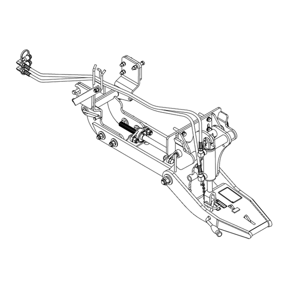
Page 24: Male Quick Hitch & Subframe
PARTS UICK ITCH AND UBFRAME OM 0421QH-A... - Page 25 PARTS UICK ITCH AND UBFRAME ESCRIPTION Subframe 669956 Front support 670262 Middle support 669958 Right rear bracket 669959 Left rear bracket 669960 Bolt hex. M12 x 1.75 x 50mm Gr.8.8 PTD 0200033 Spacer 669962 Male quick hitch ass'y 667036 Pivot Bushing 1 3/4", PTD 665826 Front "L"...
-
Page 26: Male Quick Hitch
PARTS UICK ITCH ESCRIPTION Male quick hitch 666967 Engagement lever 657681 Quick hitch latch 657676 Pin 1/4" x 1 5/8" PTD 657384 Spring plate 657383 Spring 657385 1500016 Cotter pin 1/8" x 1", PTD 1500032 Cotter pin 5/64" x 1", PTD 0100040 Bolt hex. -
Page 27: Mid Pto Drive Kit - Ls3150-C
PARTS PTO D – LS3150-C RIVE ESCRIPTION 4700002 Fixed driveline Male half driveline 4700036 Output shaft 1" x 19 3/4" lg 4700057 Ball bearing 1" assembly (#5 and #6 incl.) 4300025 654106 - Grease fitting 1/4" NF 0500003 - Setscrew 1/4" NF x 1/4" lg (incl. in / bearing) Bolt hex. -
Page 28: Fixed Driveline
PARTS RIVELINE IXED ESCRIPTION Fixed driveline 4700002 Yoke repair kit 658113 Spring lock yoke ass'y 658251 Universal joint kit 654478 Yoke and shaft ass'y 665238 Driveline Yoke 656492 OM 0421QH-A... -
Page 29: Driveline - Male Half
PARTS – M RIVELINE ESCRIPTION PART Driveline ass'y – male part 4700036 Quick disconnect yoke ass'y 658251 Yoke repair kit 658113 Universal joint kit 654478 Yoke and male shaft ass'y 660888 Nylon repair kit 661555 Outer shield 660906 OM 0421QH-A... -
Page 30: Torque Specification Table
TORQUE SPECIFICATION TABLE GENERAL SPECIFICATION TABLE Use the following torques when special torques are not given. NOTE: These values apply to fasteners as received from supplier, dry, or when lubricated with normal engine oil. They do not apply if special graphited or moly sidulphide greases or other extreme pressure lubricants are used. - Page 31 TORQUE SPECIFICATION TABLE OM 0421QH-A...
- Page 32 Printed in Canada...
Need help?
Do you have a question about the LS3150-B and is the answer not in the manual?
Questions and answers