Table of Contents
Advertisement
Advertisement
Table of Contents

Related Manuals for LS tractor LW3150


Summary of Contents for LS tractor LW3150
- Page 1 ’ ’ " " SERIAL NUMBER 21800001 AND UP FOR MT1 SERIES TRACTORS OM 0467SB-A Rev0 12-17...
-
Page 3: Introduction
INTRODUCTION TO THE DEALER TO THE PURCHASER Give this manual to the owner upon delivery of the All products are designed to give safe, dependable equipment. service if they are operated and maintained TO THE PURCHASER AND THE DEALER according to instructions. Read and understand this manual before operation, and keep it in Illustrations your files for further reference. - Page 4 INTRODUCTION All products are designed to give safe, dependable service if they are operated and maintained according to instructions. Read and understand this manual before operation. It is the owner's responsibility to be certain anyone operating this product reads this manual, and all other applicable manuals, to become familiar with this equipment and all safety precautions.
-
Page 5: Table Of Contents
TABLE OF CONTENT INTRODUCTION ............................1 TABLE OF CONTENT ..........................3 SAFETY INFORMATION ..........................5 GENERAL SAFETY INFORMATION- Pictograms ..................7 SPECIFICATIONS ............................9 SAFETY LABELS ............................10 ASSEMBLY ..............................12 Snowblower Assembly ........................12 Chute Installation ......................13 Installation of the Front Rotation Support ................13 Installation of the Manual Rotation Support on the Tractor .......... - Page 6 TABLE OF CONTENT MAINTENANCE ............................24 Maintenance ............................24 Gearbox and Reduction Box ....................25 Shearbolts .......................... 25 Auger Repositioning ......................26 Drive Chain Adjustment ..................... 26 Maintenance Schedule ........................27 Lubrication ............................27 STORAGE ..............................28 PARTS ................................ 29 Snowblower - Rear ..........................
-
Page 7: Safety Information
SAFETY INFORMATION Children Tragic accidents can occur if the operator is 4. For your safety, do not work under any not alert to the presence of children. Children hydraulically supported machine elements, they are generally attracted to machines and the creep down, suddenly... - Page 8 SAFETY INFORMATION 17. Check all machine controls regularly and 8. Park the machine/implement on level ground, adjust where necessary. Make sure that the place the transmission in neutral, set the parking brakes are evenly adjusted. Periodically brake, disengage the driving system, lower the check all nuts and bolts for tightness, equipment to the ground, place all levers especially wheel hub and rim nuts.
-
Page 9: General Safety Information- Pictograms
GENERAL SAFETY INFORMATION OM 0467SB-A... - Page 10 GENERAL SAFETY INFORMATION (1) Safety stand 2) Secure point for safety stand OM 0467SB-A...
-
Page 11: Specifications
SPECIFICATION Features and Specifications 39002748 – LW3150 Counter clockwise Type Overall width 50" Overall height (without chute) 21" Overall height (with chute) 46" Overall length (without female hitch) 22 1/2" Overall length (with female hitch) 30 3/4" Working width 49 3/4"... -
Page 12: Safety Labels
657761 2500869 LW3150 657762 2501031 657346 LS Tractor 2500879... - Page 13 ESTIMATED ASSEMBLY TIME Refer to the following table for the estimated assembly time to open the package and assemble the equipment. 50" Snowblower 39002748 Estimated initial installation time 25-35 min Reinstallation (on the tractor) 2-3 min The assembly times of the table are only a reference under normal conditions according to the following assumptions: 1.
-
Page 14: Assembly
ASSEMBLY NOWBLOWER SSEMBLY The snowblower is pre-assembled at the factory; however, parts in the bag and box must be assembled. Use the present manual and lay out all parts for assembly. Separate bolts and nuts into various sizes. After assembly, torque all the bolts according to the "Torque Specification Table" enclosed at the end of the manual. -
Page 15: Chute Installation
ASSEMBLY Chute Installation Installation of the Front Rotation Support 1. Figure 1: Place the rotation bushing (item 1) If electric or hydraulic rotation was selected, go to over the fan output with the marker (item 2) step "Connecting the Snowblower" facing up and towards the left side of the 1. -
Page 16: Installation Of The Manual Rotation Support On The Tractor
ASSEMBLY Installation of the Manual Rotation Support on the Tractor 1. Figure 3: Disconnect the female quick couplers (item 1) from the tractor valve and install the protective caps. And install the protective caps on the male quick couplers of the tractor valve. 2. -
Page 17: Installation Of Manual Rotation On The Tractor
ASSEMBLY Storing Pins and the Handle Installation of Manual Rotation on the Tractor 1. Figure 5: Figure 5: Insert the pins 1 "x 3 7/8" (item 1) into the holes (item 2A) of the 1. Figure 6: Insert the plastic grommet (item 5) snowblower hitch. -
Page 18: Procedure For Connecting And Disconnecting The Snowblower
ASSEMBLY Procedure for Connecting and Disconnecting the Snowblower PRECAUTIONS BEFORE CONNECTION TO FOLLOW EACH 1. Make sure the area is clear of any object 6. Figure 7: Make sure the equipment half driveline that could interfere with the connection. (item 5) is secure on the guard’s "U" support (item 6). -
Page 19: Procedure To Follow To Connect The Snowblower
ASSEMBLY PROCEDURE TO FOLLOW TO CONNECT THE SNOWBLOWER IT'S IMPORTANT TO FOLLOW THESE STEPS IN THE ORDER INDICATED. Step 1 Figure 8 : Start the tractor, remove the parking brake and advance slowly making sure to align the equipment female hitch with the male hitch of the tractor. - Page 20 ASSEMBLY Step 5 Figure 10 Figures 10-11: Place the male driveline (item 14) under the subframe (item 16) and insert in the equipment female driveline (item 15). Attach the male driveline (item 14) to the subframe output shaft (item 17). To do so, disengage the locking collar (item 14a) by pulling it back and push on the yoke (item 14b) to connect the driveline to the subframe output shaft (item 17).
-
Page 21: Precautions To Follow Before Each Disconnection
ASSEMBLY PRECAUTIONS BEFORE DISCONNECTION TO FOLLOW EACH 1. Make sure the area is clear of any object that could interfere with the disconnection. 2. Follow the safety measures for operating the tractor. 3. Make sure the tractor PTO is disengaged. PROCEDURE TO FOLLOW TO DISCONNECT THE SNOWBLOWER IT'S IMPORTANT TO FOLLOW THESE STEPS IN THE ORDER INDICATED. -
Page 22: Operation
OPERATION ENERAL REPARATION WARNING: To avoid serious personal injury: Do not use your hands to unclog the 1. Read the operator's manual carefully before chute. Use a 36" (925mm) stick or board. Do using tractor snowblower. not attempt to unclog the chute while engine is thoroughly familiar with the controls and running. -
Page 23: Operation
OPERATION PERATION Engine Speed 1. Start the tractor engine. Let the engine warm up at least one minute before engaging the drive mechanism then increase speed gradually. 2. Make sure the snowblower head is properly positioned and engage the drive mechanism. 3. -
Page 24: Adjustments
OPERATION DJUSTMENTS WARNING To avoid serious personal injury or death: ake sure tractor engine and snowblower come to a complete stop and tractor drive mechanism is disengaged BEFORE making Figure 14 any adjustments. Deflector Adjustment The deflector angle must be set according to the distance the snow must be thrown. -
Page 25: Snow Removal Method
OPERATION NOW REMOVAL METHODS When removing snow, do not use the snowblower as a dozer blade to push snow. Let the snowblower work its way through deep drifts. If the speed of your tractor is too fast, the snowblower may become overloaded and clog. -
Page 26: Maintenance
MAINTENANCE AINTENANCE ALWAYS USE GENUINE PARTS WHEN 4. Keep the tractor/snowblower clean. Snow, dirt REPLACEMENT PARTS ARE or ice build-up can lead to malfunction or REQUIRED personal injury from thawing and refreezing in garage. 5. Always wear eye protection when cleaning or WARNING servicing the snowblower or subframe. -
Page 27: Gearbox And Reduction Box
MAINTENANCE Gearbox & Reduction Box When servicing the gearbox, the tightness of the casing must be restored. To do so, apply a layer of silicone to the casing before closing it. Allow the silicone to cure for at least 24 hours before filling it with oil. -
Page 28: Auger Repositioning
MAINTENANCE Auger Repositioning Drive Chain Tension Adjustment (Figure 16) (Figure 17) After shear bolt breakage on one of the IMPORTANT : The chain must be adjusted after augers, make sure to reposition the augers the first 8 hours of operation and every 24 hours as shown on the figure below. -
Page 29: Maintenance Schedule
MAINTENANCE UBRICATION Use a grease gun and lubricate as follows: ESCRIPTION NTERVAL EQUIRED UBRICATION 8 hours Grease each universal joint Driveline Separate the sliding parts and cover each of 24 hours them with grease 4 hours Drive chain Lubricate with chain saw lubricant after each operation 24 hours of operation or Inject grease in grease fitting of each auger... -
Page 30: Storage
STORAGE TORAGE Before storing snowblower, certain precautions should be taken to protect it from deterioration. 1. Clean subframe snowblower thoroughly. 2. Make all the necessary repairs. 3. Replace all safety signs that are damaged, lost, or otherwise become illegible. If a part to be replaced has a label on it, obtain a new safety label from your dealer and install it in the same place as on the removed part. -
Page 31: Parts
PARTS NOWBLOWER DESCRIPTION PART# HOUSING 670910 FEMALE 4-POINT HITCH 671930 SKID SHOE 670918 CUTTING EDGE 659862 HEX. BOLT 1/2"NC X 1 1/4" GR.5 PTD 0100069 LOCKWASHER 1/2" PTD 1200006 NYLON INSERT NUT 1/2"NC PTD 1000011 CARRIAGE BOLT 5/16"NC X 3/4" PTD 0300002 LOCKWASHER 5/16"... -
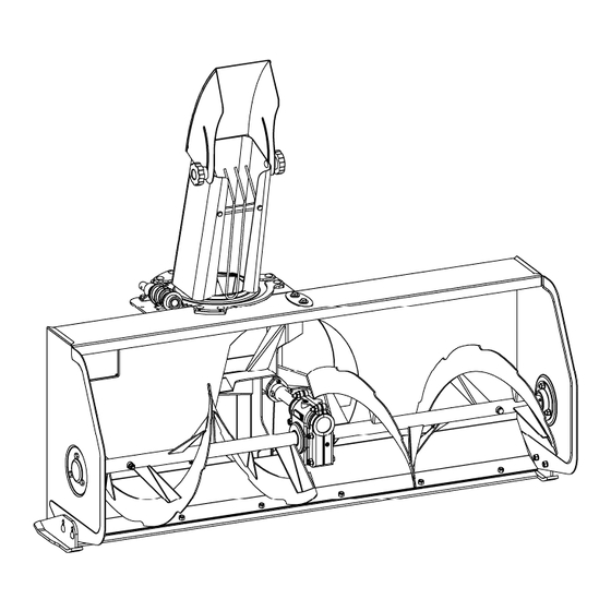
Page 32: Snowblower - Front
PARTS NOWBLOWER RONT DESCRIPTION PART# FAN INCLUDING THE 2 BUSHINGS 670915 - OILITE BUSHING 4300055 SHEAR PLATE 655874 AUGER - RH 666737 AUGER - LH 666738 GEARBOX SUPPORT 657492 REINFORCEMENT PLATE 670919 OUTPUT SHAFT 660390 BEARING FLANGE 657334 GEARBOX CCW 4500037 TRIANGULAR BEARING FLANGE - 3 HOLES 656589... - Page 33 PARTS NOWBLOWER RONT FIG: RAD15XXXXX OM 0467SB-A [31]...
-
Page 34: Reduction Box
PARTS EDUCTION DESCRIPTION PART# REDUCTION BOX ASS'Y INC. BEARINGS 657353 DRIVE SHAFT WITH SPROCKET (H40C11) 657250 BALL BEARING WITH SETSCREW 665494 TRIANGULAR BEARING FLANGE - 3 HOLES 656589 CARRIAGE BOLT 5/16"NC X 5/8" GR. 5 PTD 0300001 LOCKWASHER 5/16" 1200003 HEX. -
Page 35: Chute And Deflector
PARTS HUTE AND EFLECTOR DESCRIPTION PART# CHUTE ASSEMBLY W/ DECALS 670911 KNOB 5/16"NC 657309 FLAT WASHER NYLON 11/32" DIA. 658467 CARRIAGE BOLT 5/16"NC X 1" GR.5 PTD 0300003 FLAT WASHER NYLON 7/16" DIA. 658468 HAND GUARD 657308 BOLT HEX. 1/4"NC X 3/4" GR.5 PTD 0100003 FLAT WASHER 1/4"... -
Page 36: Manual Chute Rotation
PARTS ANUAL HUTE OTATION DESCRIPTION PART# PLASTIC BUSHING 1 5/16" 657335 ROTATION WORM 665037 REAR ROTATION WORM SUPPORT 670916 ROTATION TUBE ASSEMBLY (INCL.#5-6-7) 665041 - UNIVERSAL BLOCK 658193 - ROTATION YOKE 659595 - SPRING PIN 1/4 X 1 1/4 1600015 PLASTIC GROMMET 657390 HANDLE... -
Page 37: Gearbox
PARTS EARBOX DESCRIPTION PART# WORM GEARBOX ASSEMBLY 4500037 CASING KIT 4500021 GEAR WORM GEAR DRIVING SHAFT 4500036 BEARING 661147 BEARING 663234 SEAL KIT (ITEM 8 AND 9) 665775 661150 BREATHER 1/8" NPT, 5 PSI, PTD 654927 PLUG 1/8" NPT, PTD 656090 SPRING PIN 5/16"... -
Page 38: Female Driveline
PARTS EMALE RIVELINE DESCRIPTION PART# DRIVELINE FEMALE HALF ASS'Y 4700044 INNER SHIELD 658511 NYLON REPAIR KIT 661555 YOKE & FEMALE SHAFT ASS'Y 4700071 UNIVERSAL JOINT KIT 4700066 YOKE 1" DIA.HOLE. 4700072 OM 0467SB-A [36]... -
Page 39: Torque Specification Table
TORQUE SPECIFICATION TABLE ENERAL SPECIFICATION TABLE SE THE FOLLOWING TORQUES WHEN SPECIAL TORQUES ARE NOT GIVEN Note:These values apply to fasteners as received from supplier dry, or when lubricated with normal engine oil. They do not apply if special graphited or moly sidulphide greases or other extreme pressure lubricants are used. These values apply to dry conditions;... - Page 40 Printed in Canada...
Need help?
Do you have a question about the LW3150 and is the answer not in the manual?
Questions and answers