
Related Manuals for domi outdoor living LGCF1620


Summary of Contents for domi outdoor living LGCF1620
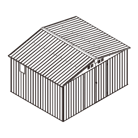
- Page 1 11'×9' Tool Storage Shed ASSEMBLY INSTRUCTIONS MODEL#: LGCF1620 Missing part? Damaged? Contact us via email at service@domioutdoorliving.com www.domioutdoorliving.com © Copyright 2022-2024 domi LLC. I All Rights Reserved.
- Page 4 List-1...
- Page 5 List-2...
- Page 6 Cross Screwdriver Hexagonal Hole Position Socket Wrench Correction Drill Gloves List-3...
- Page 8 1# x48 ①:Use part#A7 to connect the bottom frame respectively, and then fix with bolt #1 and gaskets as shown.
- Page 9 9# x4 1# x16 C3 x2 Plastic Gaskets Plastic Gaskets ①:Insert part #A to the corners. ②:Fix with 4 bolts #1 & gaskets. ② ① ③ ③:You need to prepare bolts by yourself to secure the frame to the ground. ⑤...
- Page 10 12# x24 Top Frame Assembly ①:Connect part #B1 & #B2, insert part #B7 & #B8 on the inside of part #B1/B2 with 6 bolts 12# and gaskets. ②: Connect part #B3 & #B4, insert part #B7 on the inside of part #B3/B4 with 6 bolts 12# and gaskets.
- Page 11 9# x4 12# x16 C4 x2 Plastic Gaskets Plastic Gaskets ①/②: Use #part #B to connect part #B5 & #B3, part #B4 & #B6, part #B5 & #B2, part #B1 & #B6, fix with 16 bolts 12# and gaskets. ② ①...
- Page 12 Section View ①: Use 10 bolts 9#, gaskets and caps to connect 2 part #H2 with part #C/J1/J1/C1 to form a front side wall panel. Section View ②: Use 10 bolts 9#, gaskets and caps to connect 2 part #H1 with part #C2/J1/J1/C to form a front side wall panel.
- Page 13 Section View Section View Place part #J on the bottom frame(#A6), using 3 bolts 1# and gaskets to fix. Attention: To ensure the stability of the wall panel(#J) during assembly, you can temporarily reinforce this position(☆) with bolts 2#, and replace it with other correct bolts when the next installation is made.
- Page 14 Use part #H7 to connect part #H3 and part #H4, and fix with bolts 3#, gaskets and nuts. Repeat the above procedures to connect part #H5 with part #H6. H5/H6...
- Page 15 Outside View Inside View Side Window Assembly: Insert part #N to the wall panel #J2 (from outside to inside), place transparent board #N2, use 8 bolts #13 to fix part #N1 & part #N (from inside to outside). Repeat the above procedures to assemble another side window.
- Page 16 1# x12 9# x8 Place part #J2/J/C on the bottom frame #A6, using 6 bolts 1# and gaskets to fix. ①: Use 2 bolts 9# and gaskets to install 2 support tubes(H6+H5) to wall panel #J, then put on the plastic caps. Front Side Back Side Side View...
- Page 17 9# x12 Place part #J1 on the bottom frame #A4, using 4 bolts 1# and gaskets to fix. Place part #J1 on the bottom frame #A3, using 4 bolts 1# and gaskets to fix. Front Side Back Side Section View Plastic Cap ③: Use 4 bolts 9# and gaskets to install 2 support tubes(H6+H5) &...
- Page 18 Side View Side View Plastic Cap Plastic Cap Use 13 bolts 1# and gaskets to fix 4 part #J on the bottom frame(A5 & A6). ①: Use 10 bolts 9# and gaskets to fix 4 part #J with 2 support tubes(H5+H6) , then put on the plastic caps to form a whole side wall.
- Page 19 ①/②: Place the assembled frame on the upper end of the wall panel, and fix with 89 bolts 1# and gaskets. ④: Fix the upper end of the part#C2 with part #C4 ③: Fix the upper end of the part#C1 (already assembled on part#B2) with part #C4(already assembled on by using bolts 3#, the gaskets...
- Page 20 Connection of the middle top beam (part #E1*2/E2*2/E5*2/E6*1) Plastic Cap Section View Connection of the side top beam (part #E3/E4/E5) Plastic Cap Section View...
- Page 21 Top Beam Assembly ①: Splice part#D1 & #D2, clamp the 2 sides with part #D; Use 3 bolts 3# (including 1 bolt ,2 gaskets and 1 nuts) to fix 2 part #D to part #D1 & #D2; Clamp the two sides with part#E1/E2, and tighten with 2 bolts 3#, gaskets nuts.
- Page 22 ②: Use 4 bolts 2#(including ③: Use 4 bolts 2#(including 1 bolt,1 gaskets and 1 nuts) 1 bolt,1 gaskets and 1 nuts) to fix part #D3 with part to fix part #D4 with part #E4 & #D1. #E3 & #D2. Repeat the above procedures to assemble another side.
- Page 23 Cross Screwdriver Place the assembled top beam on the top frame, tighten with 28 bolts #1 and gaskets.
- Page 24 Assemble part #G2 to the one side of part #K2 with 6 bolts 2# gaskets and nuts. Assemble part #G1 to the one side of part #K1 with 6 bolts 2# gaskets and nuts. Section View...
- Page 25 Attention: The top plate can be installed in order or reverse order. If there is a deviation between the top plate and the top frame installation hole, it is generally caused by the diagonal size deviation of the frame beam. The diagonal distance of the frame beam can be measured and adjusted.
- Page 26 Plastic Cap Plastic Cap ①: Secure the roof panel to ②: Part #Z shall be inserted at the gap the main top beam with 42 between roof panels and side top beam, self-tapping bolts 4# and then fix with 20 self-tapping bolts #5 part #Z.
- Page 27 ③: The roof panel K1/K2 is fixed with top frame D1/D2 by using 20 bolts 2#, gaskets and nuts. ④: The roof panel is fixed to the side top frame (B5,B6) by using 42 self-tapping bolts #1 and gaskets.
- Page 28 ①: Use 2 bolts 3#, 4 gaskets and 2 nuts to fix part #F with part #K1/K2 and part #D1/D2. Use 2 bolts 3#, 4 gaskets and 2 nuts to fix part #F3 with part #K1/K2 and part #D1/D2. Section View ②: Insert part #Z into the roof panel groove, use 4 bolts 11#, 8 gaskets and 4 nuts to fix part #F2 and part #F/#F3 to the roof top.
- Page 29 ③: Step.1: Use 21 bolts 2# gaskets and nuts to fix part #G3 and #G4 on the cornice of roof panel. Step.2:Use 4 bolts 2#,gaskets and nuts to cover part #G7 on the connection of part #G3 & #G4. Repeat the above producers to assemble another side.
- Page 30 ①/②: Install part #G5/G6 to 4 corners of the roof, fix with 8 bolts #3, 16 gaskets and 8 nuts. ③: Use 4 bolts 7# to install part #F1 from inside. Repeat the above procedure to assemble another side.
- Page 31 The front side of left door The back side of left door Installation diagram of door panel, Section View frame and screw...
- Page 32 The back side of right door The front side of right door Installation diagram of door panel, Section View frame and screw...
- Page 33 There is a latch on the left door There is a handle on the right door ①: This section is need to installed by the user. Lining board #Y is on the inside The hinge has been pre-installed on the of the door frame.
- Page 34 ①/②: Insert the latch and lock the left door. ③: Open the door: insert the key, rotate 180 counterclockwise, and rotate the handle counterclockwise to open the door. Lock the door: close the door, insert the key, rotate the handle clockwise, then rotate the key 180 clockwise and pull the key out.
Need help?
Do you have a question about the LGCF1620 and is the answer not in the manual?
Questions and answers
I need 8 * 10 feet assembly instruction?
The assembly instructions for the Domi Outdoor Living LGCF1620 11×9 feet tool storage shed include the following steps:
1. Bottom Frame Assembly:
- Use part #A7 to connect the bottom frame.
- Fix with bolt #1 and plastic gaskets.
- Insert part #A into the corners and secure with 4 bolts #1 and gaskets.
- Use your own bolts to secure the frame to the ground.
2. Top Frame Assembly:
- Connect parts #B1 and #B2, insert parts #B7 and #B8 inside, and fix using 6 bolts #12 and gaskets.
- Connect parts #B3 and #B4, insert part #B7 inside, and fix with 6 bolts #12 and gaskets.
3. Wall and Support Tube Installation:
- Place part #J1 on the bottom frame (#A3 and #A4), secure with 4 bolts #1 and gaskets each.
- Use 4 bolts #9 and gaskets to install support tubes (H4+H3 and H6+H5) to part #C and wall panels #J1.
- Use plastic caps after installation.
4. Roof Panel Installation:
- Fix roof panels K1/K2 to top frames D1/D2 using 20 bolts #2, gaskets, and nuts.
- Fix roof panels to side top frames B5/B6 using 42 self-tapping bolts #1 and gaskets.
- Use bolts #3, gaskets, and nuts to fix parts #F and #F3 with parts K1/K2 and D1/D2.
- Insert part #Z into the roof panel groove and fix with bolts #11, gaskets, and nuts.
5. Cornice Installation:
- Fix parts #G3 and #G4 to the roof panel cornice using 21 bolts #2, gaskets, and nuts.
- Cover connections with part #G7 using 4 bolts #2, gaskets, and nuts.
6. General:
- Use a cross screwdriver, socket wrench, gloves, and drill.
- Plastic caps are used to cover bolts after installation.
Ensure all bolts and gaskets are correctly placed and tightened during each step.
This answer is automatically generated