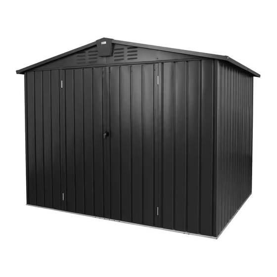
Summary of Contents for domi outdoor living LGCF1551
- Page 1 s e r v i c e @ d o mi o u t d o o r l i v i n g . c o m 2 0 1 9 - 2 0 2 3 D o mi O u t d o o r L i v i n g L L C . A l l R i g h t s R e s e r v e d .
- Page 9 Step 1:Use 6 screws 9#, gaskets and caps to connect 2 part H2 with part #C/J1/C1 as shown in ① to form a front side wall panel. Step 2: Place the assembled front side wall panel (C/J1/C1) on the bottom frame(A1), using 5 screws 1# and gaskets to fix.
- Page 10 S i d e V i e w...
- Page 11 Step 1: Place part #J1/C/J on the bottom frame (A6/A4), using 7 screws 1# and gaskets to fix. Step 2: Use 2 screws 9# and gaskets to install 2 part#(H5+H6)with part#C & J1, then put on the plastic caps as shown in ①. Step 3: Use 2 screws 9# and gaskets to install 2 part#(H5+H6)with part#J1 &...
- Page 12 Step 1: Use 7 screws 1# and gaskets to fix 2 part#J on the bottom frame(A5 & A6). Step 2: Use 6 screws 9# and gaskets to fix 2 part#J with 2 part#(H5+H6), then put on the plastic caps to form a whole side wall as shown in ①②. Repeat the above procedures to assemble another side wall.
- Page 13 Step1: Connect part #B1 and part #B2, insert part #B7 & B8 on the inside of part #B1/B2 with 6 screws 12# and gaskets as shown in ①. Step2: Connect part #B3 and part #B4, insert part #B7 on the inside of part #B3/B4 with 6 screws 12# and gaskets as shown in ②.
- Page 14 E n c l o s e w i t h p a r t # B 5 / B 3 , p a r t # B 4 / B 6 , p a r t # B 5 / B 2 , p a r t # B 1 / B 6 , a c c o r d i n g t o t h e fi g u r e a b o v e , a n d t h e p a r t # B c o n n e c t s t h e f o u r c o r n e r s , t h e n fi...
- Page 15 P l a c e t h e a s s e mb l e d b e a m ( B 1 , B 2 , B 3 , B 4 , B 5 , B 6 ) o n t h e u p p e r e n d o f t h e w a l l p a n e l , a n d f i x w i t h 5 9 s c r e w s 1 # a n d g a s k e t s a s s h o w n i n ①②.
- Page 19 Assemble the part#G2 to the one side of part#K4 with 4 screws 2# gaskets and nuts. Assemble the part#G1 to the one side of part#K1 with 4 screws 2# gaskets and nuts.
- Page 20 The roof panel K1/K4 is fixed with top frame D1/D2 by using screws 2#,gaskets and nuts as shown in ③,then fix with screw 1# and gaskets to side top beam as shown in ④.
- Page 22 Step1:Install the part #F: Step2:Use 4 screws 3#,gaskets Insert part #Z into the top panel and nuts to fix the 2 sides of groove, use 4 screws 11#,gaskets part #F with part #K1/K4 and nuts to fix part#F2 and part #F and part #D1/D2 as shown in ①.
- Page 23 Step1: Use 14 screws 2# gaskets and nuts to fix part #G3 and part#G4 on the cornice of top roof. Step2: Use 4 screws 2#,gaskets and nuts to cover part #G7 on the connection of part #G3 and part#G4 as shown in ③. Repeat the above producers to assemble the another side.
- Page 29 s e r v i c e @d o mi o u t d o o r l i v i n g . c o m 2 0 1 9 - 2 0 2 3 D o mi O u t d o o r L i v i n g L L C . A l l R i g h t s R e s e r v e d .


Need help?
Do you have a question about the LGCF1551 and is the answer not in the manual?
Questions and answers