Table of Contents
Advertisement
Quick Links
Advertisement
Table of Contents

Related Manuals for Planet XT-715A


Summary of Contents for Planet XT-715A
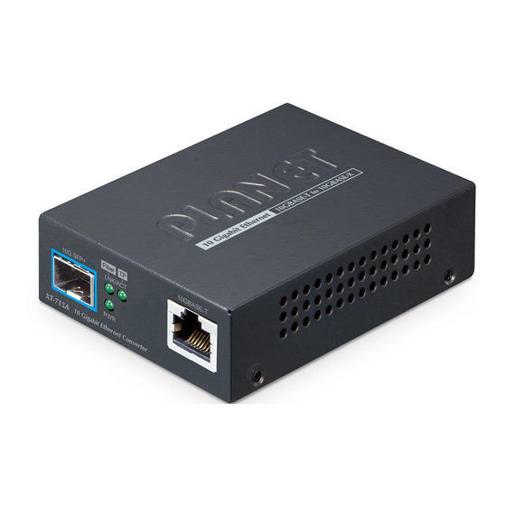
- Page 1 10GBASE-T to 10GBASE-X SFP+ Media Converter XT-715A User's Manual...
- Page 2 PLANET has made every effort to ensure that this User’s Manual is accurate; PLANET disclaims liability for any inaccuracies or omissions that may have occurred.
- Page 3 Do not dispose of WEEE as unsorted municipal waste and have to collect such WEEE separately. Revision PLANET 10GBASE-T to 10GBASE-X SFP+ Media Converter User’s Manual Model: XT-715A Revision: 1.0 (November, 2023) Part No: EM-XT-715A_v1.0 (2351-AA5430-000)
-
Page 4: Table Of Contents
3.3 Media Chassis Installation ............. 15 3.4 Optional DIN-rail Installation ............16 3.5 Cable Connection ................. 17 APPENDIX A: Approved PLANET SFP+ Transceivers ........20 APPENDIX B: Networking Connection ............22 B.1 Media Converter’s RJ45 Pin Assignments ........22 B.2 RJ45 Cable Pin Assignments ............22... -
Page 5: Introduction
The XT-715A comes with one vacant SFP module slot. The mini GBIC SFP module is not included in the package. -
Page 6: Product Features
External 5V DC, 2A power input socket Wall mounting or DIN-rail installation (optional) 0 to 50 degrees C operating temperature Compact in size, Plug and Play installation Best with PLANET’s 10”/19” Media Converter Chassis (MC-700/MC-1500/ MC-1500R/MC-1500R48) -
Page 7: Product Specifications
1.3 Product Specifications Model XT-715A Interface 2.5G/5G/10GBASE-T Ethernet RJ45 interface Copper Port Auto-negotiation, auto MDI/MDI-X SFP Interface 10GBASE-X SFP+ interface Fiber Mode May vary on SFP Module Fiber Port Type SFP, LC type (connector) Fiber Maximum May vary on SFP Module Distance 2.5G/5G/10GBASE-T:... - Page 8 Layer 2 Features Forwarding Rate Non-blocking full wire-speed forwarding rate Back pressure for half duplex mode Flow Control IEEE 802.3x pause frame for full duplex mode Maximum Frame Size Standards Conformance Regulatory FCC Part 15 Class A, CE Compliance IEEE 802.3bz 2.5G/5GBASE-T Protocols and IEEE 802.3an 10GBASE-T Standards...
-
Page 9: Hardware Description
2. Hardware Description 2.1 Physical Dimensions z XT-715A dimensions (W x D x H): 93.5 x 70 x 26 mm 10 Gigabit Ethernet 10GBASE-T to 10GBASE-X Unit: mm Figure 2-1: XT-715A Physical Dimensions... -
Page 10: Converter Front Panel And Led Indicators
Figure 2-2 shows the front panel of the Media Converter. 10GBASE-T Fiber 10G SFP+ LNK/ACT XT-715A 10 Gigabit Ethernet Converter Figure 2-2: XT-715A Front Panel System Color Function Lights to indicate the 10G Media Converter has power. Green 10GBASE-X SFP+ Interface... -
Page 11: Rear Panel
2.3 Rear Panel The rear panel of the XT-715A consists of one DC jack, which accepts input power with 5V DC, 2A. 5V DC Figure 2-3: One DC jack for DC power input 2.4 Power Information: The central pole of the Media Converter’s power jacks measures 2.5mm wide that requires +5VDC power input. - Page 12 The device is a power-required device, meaning it will not work till it is powered. If your networks should be active all the time, please consider using UPS (Uninterrupted Power Supply) for your device. It will prevent you from network data loss or network downtime. In some areas, installing a surge suppression device may also help to protect your Media Converter from being damaged by unregulated surge or current to the converter or the power adapter.
-
Page 13: Installation
Please read this chapter completely before continuing. 3.1 Stand-alone Installation Step 1: Unpack the Media Converter. Step 2: Connect the 5V DC power adapter to the XT-715A and verify that the Power LED lights up. (Please refer to the 2.4 Power Information section for power input.) -
Page 14: Wall-Mount Installation
Step 5: When all the connections are all set and the LED lights all show normal, the installation is completed. 1. Install the 10G SFP+ transceiver into the media converter 10G SFP+ slot; the 10G SFP+ slot LNK/ACT LED will light on (Chipset restriction). -
Page 15: Media Chassis Installation
Step 4: Refer to Chapter 2.4 Power Information on power supply to the Media Converter. Before mounting the device to the wall, please check the loca- tion of the electrical outlet and the length of the Ethernet cable. 3.3 Media Chassis Installation To install the Media Converter in a 10-inch or 19-inch standard rack, follow the instructions described below. -
Page 16: Optional Din-Rail Installation
3.4 Optional DIN-rail Installation There are two DIN-rail holes on the left side of the XT-715A that allows to be easily installed by DIN-rail mounting. PLANET optional DIN-rail mounting kit – RKE-DIN -- can be ordered separately. Refer to the following steps for the DIN-rail mounting of the XT-715A: Step 1: Screw the DIN rail on the XT-715A. -
Page 17: Cable Connection
Media Converter MTB Series Transceiver Figure 3-2: Plug in the SFP+ Transceiver It is recommended to use PLANET SFP+ transceiver on the Media Converter. If you insert an SFP+ transceiver that is not supported, the Media Converter will not recognize it. - Page 18 2. Check whether the fiber-optic cable type matches the SFP+ transceiver model. To connect to 10GBASE-SR SFP+ transceiver, use the multi-mode fiber cable with one side being the male duplex LC connector type. To connect to 10GBASE-LR SFP+ transceiver, use the single-mode fiber cable with one side being the male duplex LC connector type.
- Page 19 2.5G/5G/10GBASE-T The 2.5G/5G/10GBASE-T port comes with auto-negotiation capability. It automatically supports 2.5GBASE-T, 5GBASE-T and 10GBASE-T networks. Users only need to plug a working network device into the 2.5G/5G/10GBASE-T port, and then turn on the Media Converter. The port will automatically run at 2500Mbps,5000Mbps and 10000Mbps after the negotiation with the connected device.
-
Page 20: Appendix A: Approved Planet Sfp+ Transceivers
APPENDIX A: Approved PLANET SFP+ Transceivers PLANET Media Converter supports 10GBASE-X with both multi-mode and single mode SFP+ transceivers. The following list of approved PLANET SFP+ transceivers are correct at the time of publication: Available 10Gbps SFP+ Transceivers MTB-RJ 1-Port 10GBASE-T SFP+ Copper Fiber Optic Module - 30m... - Page 21 1-Port 10GBASE-BX SFP+ Fiber Optic Module - 60km MTB-LA60 (TX:1270nm RX:1330nm) 1-Port 10GBASE-BX SFP+ Fiber Optic Module - 60km MTB-LB60 (TX:1330nm RX:1270nm) 1-Port 10GBASE-BX SFP+ Fiber Optic Module - 70km MTB-LA70 (TX:1270nm RX:1330nm) 1-Port 10GBASE-BX SFP+ Fiber Optic Module - 70km MTB-LB70 (TX:1330nm RX:1270nm)
-
Page 22: Appendix B: Networking Connection
APPENDIX B: Networking Connection B.1 Media Converter’s RJ45 Pin Assignments 2.5G, 5G and 10GBASE-T Contact MDI-X BI_DA+ BI_DB+ BI_DA- BI_DB- BI_DB+ BI_DA+ BI_DC+ BI_DD+ BI_DC- BI_DD- BI_DB- BI_DA- BI_DD+ BI_DC+ BI_DD- BI_DC- B.2 RJ45 Cable Pin Assignments... - Page 23 The standard RJ45 receptacle/connector There are 8 wires on a standard UTP/STP cable and each wire is color-coded. The following shows the pin allocation and color of straight cable and crossover cable connection: Straight Cable SIDE 1 SIDE 2 1 = White/Orange 1 = White/Orange 1 2 3 4 5 6 7 8 SIDE 1...
Need help?
Do you have a question about the XT-715A and is the answer not in the manual?
Questions and answers