Cisco Firepower 9300 Hardware Installation Manual
Hide thumbs
Also See for Firepower 9300:
- User manual ,
- Hardware installation manual (84 pages) ,
- Installation & maintenance (36 pages)
Table of Contents
Advertisement
Quick Links
Advertisement
Table of Contents

Related Manuals for Cisco Firepower 9300


Summary of Contents for Cisco Firepower 9300
- Page 1 Cisco Firepower 9300 Hardware Installation Guide First Published: 2015-07-16 Last Modified: 2021-09-13 Americas Headquarters Cisco Systems, Inc. 170 West Tasman Drive San Jose, CA 95134-1706 http://www.cisco.com Tel: 408 526-4000 800 553-NETS (6387) Fax: 408 527-0883...
- Page 2 Cisco has more than 200 offices worldwide. Addresses and phone numbers are listed on the Cisco website at www.cisco.com/go/offices. Cisco and the Cisco logo are trademarks or registered trademarks of Cisco and/or its affiliates in the U.S. and other countries. To view a list of Cisco trademarks, go to this URL: https://www.cisco.com/c/en/us/about/legal/trademarks.html.
-
Page 3: Table Of Contents
Hardware Bypass Network Modules 40-Gb Network Module with Hardware Bypass 10-Gb SR/10-Gb LR Network Module with Hardware Bypass Power Supply Modules Fan Modules Supported SFP/SFP+ and QSFP Transceivers Hardware Specifications Product ID Numbers Power Cord Specifications Cisco Firepower 9300 Hardware Installation Guide... - Page 4 Install, Remove, and Replace the Double-Wide Network Module Remove and Replace the Power Supply Module Connect the DC Power Supply Module Connect the HVDC Power Supply Module Remove and Replace the Fan Module Install the FIPS Opacity Shield Cisco Firepower 9300 Hardware Installation Guide...
-
Page 5: Overview
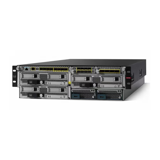
Power Cord Specifications, on page 36 Features The Cisco Firepower 9300 security appliance is a next generation network and content security platform. Its modular standalone chassis offers high-performance and flexible I/O options, which enable it to run multiple security services simultaneously. - Page 6 Overview Features Figure 1: Firepower 9300 The following table lists the hardware features of the Firepower 9300. Table 1: Firepower 9300 Features Feature Description Security standards • Criteria Common Criteria Certification (CC) for the Network Device certifications Collaborative Protection Profile (NDcPPv2.1) for ASA 9.12.x and FX-OS 2.6.x...
- Page 7 • 4-port 100-Gigabit Ethernet QSFP28 • 2-port 40-Gigabit Ethernet QSFP+ (built-in) with hardware bypass • 6-port 10-Gigabit Ethernet SR/LR fiber SFP+ (built-in) with hardware bypass You can deploy the Firepower 9300 as a dedicated threat sensor with Note hardware bypass network modules.
-
Page 8: Chassis Components
Locator beacon On front panel Power switch On rear panel Note The initial Firepower 9300 chassis does not have a power switch. Power supply slots On rear panel Power supply types AC, DC, and HVDC Do not mix power supply types or wattage. - Page 9 10 seconds before turning power back ON. The Firepower 9300 chassis has a standby power switch at the rear of the chassis. It controls both power supply modules. You must shut down the software applications gracefully before turning the switch to OFF.
-
Page 10: Deployment Options
• As a leaf that exclusively offers security functions in a spine/leaf data center design. Package Contents The following figure shows the package contents for the Firepower 9300. Note that the contents are subject to change and your exact contents might contain additional or fewer items. - Page 11 Overview Package Contents Figure 2: Firepower 9300 Package Contents Firepower 9300 chassis Blue console cable PC terminal adapter Two power cords (country specific) Two rack static rails Adjusts to fit racks with a 24 in. to 36 in. front-to-rear rail span Four 10-32 x .5 in.
-
Page 12: Serial Number Location
Serial Number Location Serial Number Location The serial number for the Firepower 9300 chassis is located on the pullout asset card on the front panel, on the side of the chassis, and on the Supervisor. Figure 3: Serial Numbers on the 9300 Chassis You can also view additional model information on the compliance label located on the bottom of the chassis. -
Page 13: Front Panel
For the procedure to remove the Supervisor so that you can see the serial number, see Remove and Replace the Supervisor, on page Front Panel The following figure shows the front panel of the Firepower 9300. Figure 5: Firepower 9300 Front Panel Cisco Firepower 9300 Hardware Installation Guide... -
Page 14: Rear Panel
Power Supply Modules, on page 26 for detailed information about the power supply modules. Rear Panel The following figure shows the rear panel of the Firepower 9300. Figure 6: Firepower 9300 Rear Panel Power feed for PSU-2 Power feed for PSU-1... -
Page 15: Supervisor
Supervisor The Firepower 9300 contains a supervisor management I/O card called the Firepower 9300 Supervisor, which is located on the front panel. The Supervisor provides chassis management and eight 1- or 10-Gb SFP+ interfaces, and it directs traffic to/from the Firepower 9300 security modules. - Page 16 RJ-45 Console Port The Firepower 9300 has a standard RJ-45 console port. You can use the CLI to configure your Firepower 9300 through the RJ-45 serial console port by using a terminal server or a terminal emulation program on a computer.
-
Page 17: Security Modules
Each port has LEDs that represent link/activity status. Management Port The Firepower 9300 chassis has a management port on the Supervisor that requires a 1-Gb fiber or copper SFP. Security Modules The Firepower 9300 has three slots for security modules. The security modules are hot-swappable. - Page 18 Overview Security Modules Figure 8: Firepower 9300 Security Module Front Panel Paper tab for server name or serial number Security module ejector handle Ejector handle captive screw SSD bay 1 SSD bay 2 Power button and LED • Off—No power.
-
Page 19: Network Modules
Network Modules The Firepower 9300 contains two network module slots that provide optical or electrical network interfaces. Network modules are optional, removable I/O modules that provide either additional ports or different interface types (1/10/40/100 Gb). -
Page 20: 10-Gb Network Module
You can fit four copper SFPs in either the top row of ports or the bottom row of ports. Both rows cannot be populated at the same time, because of the port row spacing. Cisco Firepower 9300 Hardware Installation Guide... -
Page 21: 40-Gb Network Module
40-Gb Network Module The following figure shows the front panel of the 40-Gb network module (FPR9K-NM-4X40G.) The FPR9K-NM-4X40G is a single-wide module that supports hot swapping. The four ports are numbered left to right. Cisco Firepower 9300 Hardware Installation Guide... - Page 22 • Green, flashing—Network activity. • 40Gb—Only the leftmost LED indicates the port status. • 4x10Gb—Each of the port LEDS indicates the status of respective 10-Gb channel. Ethernet X/1 Ethernet X/2 Ethernet X/3 Ethernet X/4 Cisco Firepower 9300 Hardware Installation Guide...
-
Page 23: 100-Gb Network Module (Two Ports, Single Wide)
• Green, flashing—Network activity. Network activity LEDs Ethernet X/1 • Off—No connection or port is not in use. • Amber—No link or network failure. • Green—Link up. • Green, flashing—Network activity. Ethernet X/2 Captive screw/handle Cisco Firepower 9300 Hardware Installation Guide... -
Page 24: 100-Gb Network Module (Four Ports, Single Wide)
Ethernet X/2 Ethernet X/3 Ethernet X/4 Captive screw/handle Network activity LEDs • Off—No connection or port is not in use. • Amber—No link or network failure. • Green—Link up. • Green, flashing —Network activity. Cisco Firepower 9300 Hardware Installation Guide... -
Page 25: 100-Gb Network Module (Double Wide)
Hardware bypass is supported only on a fixed set of ports. You can pair Port 1 with Port 2, Port 3 with Port 4, but you cannot pair Port 1 with Port 4 for example. Cisco Firepower 9300 Hardware Installation Guide... - Page 26 40-Gb network module. • See 10-Gb SR/10-Gb LR Network Module with Hardware Bypass, on page 24 for a description of the 1-Gb SX, 10-Gb SR and LR network modules. Cisco Firepower 9300 Hardware Installation Guide...
-
Page 27: 40-Gb Network Module With Hardware Bypass
Bypass LED BP: Ethernet X/2 • Green—In standby mode. Ports 1 and 2 are paired together to form a hardware bypass pair. • Amber, flashing—Port is in hardware bypass mode, failure event. Cisco Firepower 9300 Hardware Installation Guide... -
Page 28: 10-Gb Sr/10-Gb Lr Network Module With Hardware Bypass
50 m cable distance Note See the Cisco 40GBASE QSFP Modules Data Sheet for specifications of the QSFP for the 40-Gb BASE-SR-4. We recommend the following Cisco OM3 MTP/MPO cables. Table 3: Cisco Cables Cisco Part Number Cable Length CAB-ETH-40G-5M... - Page 29 Table 4: 10-Gb SR Network Module (FPR9K-NM-6X10SR-F) Operating Mode Typical Maximum Insertion loss Normal 0.9 dB 1.4 dB Hardware bypass 1.2 dB 1.7 dB Cisco Firepower 9300 Hardware Installation Guide...
-
Page 30: Power Supply Modules
Power Supply Modules The Firepower 9300 supports two AC, two DC, or two high-voltage DC (HVDC) power supply modules so that dual power supply redundancy protection is available. Facing the front of the chassis, the power supply modules are numbered left to right, for example, PSU-1 and PSU-2. - Page 31 10 seconds before turning power back ON. The following table describes the DC power supply LEDs. Table 7: DC Power Supply Module LEDs Input DC Power -48V Power Switch Position Green LED Amber LED No input DC power Cisco Firepower 9300 Hardware Installation Guide...
-
Page 32: Fan Modules
Fan Modules The Firepower 9300 requires four fan modules, which are hot-swappable. They are installed in the rear of the chassis. When you remove a fan module, make sure you replace it quickly to avoid overheating the system. - Page 33 Transmit optical bore Caution Although non-Cisco SFPs are allowed, we do not recommend using them because they have not been tested and validated by Cisco. Cisco TAC may refuse support for any interoperability problems that result from using an untested third-party SFP transceiver.
- Page 34 10G AOC, 2m SFP-10G-AOC2M 10G AOC, 3m SFP-10G-AOC3M 10G AOC, 5m SFP-10G-AOC5M 10G AOC, 7m SFP-10G-AOC7M 10G AOC, 10m SFP-10GAOC10M 40 Gb 40G-SR4 QSFP-40G-SR4 40G-SR4-S QSFP-40G-SR4-S 40G-CSR4 QSFP-40G-CSR4 40G-SR-BD QSFP-40G-SR-BD 40GE-LR4 QSFP-40GE-LR4 40GE-LR4-S QSFP-40GE-LR4-S Cisco Firepower 9300 Hardware Installation Guide...
-
Page 35: Hardware Specifications
100-Gb single-wide network modules (FPR-NM-2X100G and FPR-NM-4X100G). Hardware Specifications The following table contains hardware specifications for the Firepower 9300. Physical Specifications for the 9300 Chassis Dimensions (H x W x D) 5.25 x 17.5 x 32 in. (13.3 x 44.5 x 81.3 cm) Weight 105 lb (47.7 kg) with one security module... - Page 36 Long Term: 0 to 35° C, 6000-13000 ft (1829-3964 m) Short Term: -5 to 55° C, up to 6000 ft (1829 m) Note Firepower 9300 NEBS compliance applies only to the SM-24 and SM-44 security module configurations. Humidity 5 to 95 % noncondensing (operating and nonoperating)
-
Page 37: Product Id Numbers
Product ID Numbers Product ID Numbers The following table lists the PIDs associated with the Firepower 9300. All of the PIDs in the table are field-replaceable. If you need to get a return material authorization (RMA) for any component, see... - Page 38 Firepower 2-port 100-Gb double-wide network module FPR9K-DNM-2X100G= Firepower 2-port 100-Gb double-wide network module (spare) FPR9K-DNM2X100G-RF Firepower 2-port 100-Gb double-wide network module, REMANUFACTURED FPR9K-NM-2X100G Firepower 2-port 100-Gb single-wide network module FPR9K-NM-2X100G= Firepower 2-port 100-Gb single-wide network module (spare) Cisco Firepower 9300 Hardware Installation Guide...
- Page 39 FPR9K-PS-AC Firepower 9000 series AC power supply module FPR9K-PS-AC= Firepower 9000 series AC power supply module (spare) FPR9K-PS-DC Firepower 9000 series DC power supply module FPR9K-PS-DC= Firepower 9000 series DC power supply module (spare) Cisco Firepower 9300 Hardware Installation Guide...
-
Page 40: Power Cord Specifications
Orders delivered to Argentina, Brazil, and Japan must have the appropriate power cord ordered with the system. Note Only the approved power cords or jumper power cords provided with the security appliance are supported. The following power cords are supported: Cisco Firepower 9300 Hardware Installation Guide... - Page 41 Figure 18: Australia CAB-AC-16A-AUS Plug: AS/NZS 3112:2011 + A1 Cord set rating: 16 A, 250 V Connector: IEC 60320/C19 Figure 19: Brazil UCSB-CABL-C19-BRZ Plug: NBR 14136 Cord set rating: 16 A, 250 V Connector: IEC 60320/C19 Cisco Firepower 9300 Hardware Installation Guide...
- Page 42 Figure 21: China CAB-AC16A-CH Plug: GB2099.1/GB1002 Cord set rating: 16 A, 250 V Connector: IEC 60320/C19 Figure 22: Europe CAB-AC-2500-EU Plug: CEE 7 VII Cord set rating: 16 A, 250 V Connector: IEC 60320/C19 Cisco Firepower 9300 Hardware Installation Guide...
- Page 43 Figure 24: International CAB-AC-2500W-INT Plug: IEC60309/219306 Cord set rating: 16 A, 250 V Connector: IEC 60320/C19 Figure 25: Israel CAB-AC-2500W-ISRL and CAB-S132-C19-ISRL Plug: SI 32 PART 1.01 Cord set rating: 16 A, 250 V Connector: IEC 60320/C19 Cisco Firepower 9300 Hardware Installation Guide...
- Page 44 Figure 27: Japan CAB-C19-C20-3M-JP Plug: EN 60320-2-2/IC20 Cord set rating: 16 A, 250 V Connector: IEC 60320/C19 Figure 28: Korea CAB-9K16A-KOR Plug: KTL SUO4007-1001 Cord set rating: 16 A, 250 V Connector: IEC 60320/C19 Cisco Firepower 9300 Hardware Installation Guide...
- Page 45 Figure 30: Switzerland CAB-ACS-16 Plug: SEV 5934-2 Cord set rating: 16 A, 250 V Connector: IEC 60320/C19 Figure 31: Twist Lock CAB-AC-C6K-TWLK Plug: NEMA L6-20P Cord set rating: 16 A, 250 V Connector: IEC 60320/C19 Cisco Firepower 9300 Hardware Installation Guide...
- Page 46 Overview Power Cord Specifications Figure 32: United Kingdom CAB-BS1363-C19-UK Plug: BS1363A Cord set rating: 13 A, 250 V Connector: IEC 60320/C19 Cisco Firepower 9300 Hardware Installation Guide...
-
Page 47: Installation Preparation
• Rack Configuration Considerations, on page 48 Installation Warnings Read the Regulatory and Compliance Safety Information document before installing the Firepower 9300. Take note of the following warnings: Warning Statement 1071 Warning Definition IMPORTANT SAFETY INSTRUCTIONS Before you work on any equipment, be aware of the hazards involved with electrical circuitry and be familiar with standard practices for preventing accidents. - Page 48 • Do not use if battery is warped or swollen. • Do not store or use battery in a temperature > 60° C. • Do not store or use battery in low air pressure environment < 69.7 kPa. Cisco Firepower 9300 Hardware Installation Guide...
- Page 49 Do not operate the system unless all cards, faceplates, front covers, and rear covers are in place. Warning Statement 1030 Equipment Installation Only trained and qualified personnel should be allowed to install, replace, or service this equipment. Cisco Firepower 9300 Hardware Installation Guide...
-
Page 50: Safety Recommendations
Then, if an electrical accident occurs, you can act quickly to turn off the power. • Do not work alone if potentially hazardous conditions exist anywhere in your work space. Cisco Firepower 9300 Hardware Installation Guide... -
Page 51: Prevent Esd Damage
• Electrical equipment generates heat. Ambient air temperature might not be adequate to cool equipment to acceptable operating temperatures without adequate circulation. Ensure that the room in which you operate your system has adequate air circulation. Cisco Firepower 9300 Hardware Installation Guide... -
Page 52: Power Supply Considerations
• In an enclosed rack with a ventilation fan in the top, heat generated by equipment near the bottom of the rack can be drawn upward and into the intake ports of the equipment above it in the rack. Ensure that you provide adequate ventilation for equipment at the bottom of the rack. Cisco Firepower 9300 Hardware Installation Guide... - Page 53 • Baffles can help to isolate exhaust air from intake air, which also helps to draw cooling air through the chassis. The best placement of the baffles depends on the airflow patterns in the rack. Experiment with different arrangements to position the baffles effectively. Cisco Firepower 9300 Hardware Installation Guide...
- Page 54 Installation Preparation Rack Configuration Considerations Cisco Firepower 9300 Hardware Installation Guide...
-
Page 55: Rack-Mount And Ground The Chassis
Check for damage and report any discrepancies or damage to your customer service representative. Have the following information ready: • Invoice number of shipper (see the packing slip) • Model and serial number of the damaged unit • Description of damage • Effect of damage on the installation Cisco Firepower 9300 Hardware Installation Guide... -
Page 56: Rack-Mount The Chassis
Upgrade, on page You can mount the Firepower 9300 in a 4-post EIA-310-D rack. The static rail adjusts to fit racks with a 24 to 36-in. span between front and rear rails. The rack-mounting posts need to be 2 to 3.5 mm thick to work with the slide rail rack mounting. - Page 57 Step 6 Set the rear of the empty Firepower 9300 chassis on the static rails. Step 7 Carefully push the empty chassis into the rack until the chassis ears sit flush to the rack posts.
- Page 58 Secure the chassis ears to the rack with the four 10-32-in. screws and retention nuts (if you did not already install them in Step 5) that were provided in the Firepower 9300 accessory kit. Cisco Firepower 9300 Hardware Installation Guide...
- Page 59 Install the FIPS opacity shield if necessary. See Install the FIPS Opacity Shield, on page 77 for the procedure. Install the cables according to your default software configuration as described in the Cisco Firepower 9300 Getting Started Guide. Cisco Firepower 9300 Hardware Installation Guide...
-
Page 60: Ground The Chassis
Statement 1025 Use Copper Conductors Only To reduce risk of fire, use copper conductors only. Step 1 Use a wire-stripping tool to remove approximately 0.75 inches (19 mm) of the covering from the end of the grounding cable. Cisco Firepower 9300 Hardware Installation Guide... - Page 61 Make sure that the lug and cable do not interfere with other equipment. Step 7 Prepare the other end of the grounding cable and connect it to an appropriate grounding point in your site to ensure adequate earth ground. Cisco Firepower 9300 Hardware Installation Guide...
- Page 62 Install the FIPS opacity shield if necessary. See Install the FIPS Opacity Shield, on page 77 for the procedure. Install the cables according to your default software configuration as described in the Cisco Firepower 9300 Getting Started Guide. Cisco Firepower 9300 Hardware Installation Guide...
-
Page 63: Installation, Maintenance, And Upgrade
Install the FIPS Opacity Shield, on page 77 Remove and Replace the Supervisor You can remove the Firepower 9300 Supervisor while the system is powered on without damage to the Supervisor hardware or system. However, because the supervisor is controlling the entire chassis, including the power system, we recommend that you use the power switch on the rear panel of the chassis to put the system in standby mode. -
Page 64: Install, Remove, And Replace The Security Module
You can remove the Firepower 9300 security module while the system is running, but we recommend that you use the power switch on the rear of the chassis to put the security module in standby mode before removal and reinstallation. - Page 65 To install a new security module, grasp the front of the security module and place your other hand under the security module to support it. Step 7 Open the handle in the front of the security module. Step 8 Gently slide the security module into the opening until you cannot push it any farther. Cisco Firepower 9300 Hardware Installation Guide...
-
Page 66: Remove And Replace The Ssd
Supervisor. Step 1 Decommission the security module. Step 2 To remove an SSD, face the front of the chassis, press the handle release on the SSD and gently pull it out of the slot. Cisco Firepower 9300 Hardware Installation Guide... -
Page 67: Install, Remove, And Replace The Single-Wide Network Module
Caution We do not recommend that you remove the network module without bringing it properly offline using the appropriate CLI commands. Cisco Firepower 9300 Hardware Installation Guide... - Page 68 Network Modules, on page 15 for more information about the other single-wide network modules. Figure 42: Firepower Network Module 10 Gb Captive screw/handle Ethernet X/1 Ethernet X/3 Ethernet X/5 Ethernet X/7 Ethernet X/2 Ethernet X/4 Ethernet X/6 Cisco Firepower 9300 Hardware Installation Guide...
- Page 69 To remove the network module, loosen the captive screw on the left of the network module, release the handle until it is fully rotated, and then gently pull the network module out of the chassis. Cisco Firepower 9300 Hardware Installation Guide...
- Page 70 Gently push on the handle until it is fully seated on the network module faceplate and the module is fully seated in the chassis. Step 7 Tighten the captive screw on the left of the network module. Step 8 Do one of the following: Cisco Firepower 9300 Hardware Installation Guide...
-
Page 71: Install,Remove,Andreplacethedouble-Widenetworkmodule
The Firepower 100-Gb network module is an optional, removable I/O module that provides two fiber 100 Gigabit Ethernet interfaces. It takes up two slots in the Firepower 9300 and supports single and multimode. Verify that your software supports hot swapping. See Cisco Firepower 4100/9300 FXOS Compatibility the software compatibility matrix. - Page 72 Save the divider in case you ever want to replace the 100-Gb double-wide network module with one or two Note single-wide network modules. Or you can order the divider kit (FPR9K-NM-DIV=), which contains two dividers, one for the original 9300 chassis and one for the newer 9300 chassis. Cisco Firepower 9300 Hardware Installation Guide...
- Page 73 Hold the 100-Gb network module in front of the double network module slot on the right side of the chassis with the handle rotated fully out. Slowly push the module into the network module slot until the handle catches on the mating feature in the chassis. The handle should engage correctly. Cisco Firepower 9300 Hardware Installation Guide...
-
Page 74: Remove And Replace The Power Supply Module
FXOS Configuration Guide to connect to the network module and make sure that it has been discovered correctly by the Firepower 9300. Remove and Replace the Power Supply Module You can remove and replace the power supply module while the system is running. Make sure that at least one of the power supply modules is active while hot-swapping. - Page 75 Tighten the captive screw on the right. Step 8 Verify the power supply module is operating correctly by checking the power supply module LED. See Power Supply Modules, on page 26 for more information. Cisco Firepower 9300 Hardware Installation Guide...
-
Page 76: Connect The Dc Power Supply Module
Using the screws, connect the green ground wires to the chassis ground terminal. Only one ground connection is required even though there may be up to 2 DC connections. Step 6 Using the screws, connect the two 2-hole lugs to the power supply module terminal block. Cisco Firepower 9300 Hardware Installation Guide... -
Page 77: Connect The Hvdc Power Supply Module
Verify power supply operation by checking the power supply LED on the front of the chassis. Power Supply Modules, on page 26 for the LED values. Connect the HVDC Power Supply Module Take note of the following warnings: Cisco Firepower 9300 Hardware Installation Guide... - Page 78 Verify that the power is off to the DC circuit on the power supply module that you are installing. Step 3 Make sure that all site power and grounding requirements have been met. Step 4 Plug the HVDC power cord into the power feeds for PSU-1 and/or PSU-2. Cisco Firepower 9300 Hardware Installation Guide...
-
Page 79: Remove And Replace The Fan Module
Remove and Replace the Fan Module You can remove and replace fan modules while the system is running. The airflow moves from front to back. Fan Modules, on page 28 for more information about the fan module. Cisco Firepower 9300 Hardware Installation Guide... - Page 80 Verify that the fan is operational by checking the fan module LED. It takes about a minute for the Fan LED to be updated. Fan Modules, on page 28 for a description of the fan module LEDs. Cisco Firepower 9300 Hardware Installation Guide...
-
Page 81: Install The Fips Opacity Shield
Crypto Officer. This procedure describes how to install the FIPS opacity shield on the front of a Firepower 9300 that is already rack-mounted. The FIPS opacity shield has an access cover that is already attached with two captive screws. - Page 82 FIPS opacity shield Rack-mount rails Step 3 Unscrew the two captive screws on the front of the access cover to remove the access cover so that you can connect the cables to the ports. Cisco Firepower 9300 Hardware Installation Guide...
- Page 83 Connect the cables to the ports. See the getting started guides listed in Step 9 for the procedure. Step 5 Run the cables through the openings on either side of the FIPS opacity shield and reattach the FIPS access cover by tightening the captive screws. Cisco Firepower 9300 Hardware Installation Guide...
- Page 84 SYS LED. When the SYS LED is solid green, the chassis has booted up successfully. Step 9 See the Cisco Firepower 9300 Getting Started Guide for further configuration information. Cisco Firepower 9300 Hardware Installation Guide...
Need help?
Do you have a question about the Firepower 9300 and is the answer not in the manual?
Questions and answers