Table of Contents
Advertisement
Quick Links
Advertisement
Table of Contents

Related Manuals for jbc PSS


Summary of Contents for jbc PSS
- Page 1 INSTRUCTION MANUAL Multiaxis Rotative PCB Support...
-
Page 2: Packing List
Ref. 0032070 Application PSS is designed to support and fix PCBs to perform soldering and desoldering jobs with or without preheaters. JBC’s rotary support can work with JBC’s PHSE Preheater. Caution: Take care when working with preheaters since metal surfaces of the support can be hot - especially the sliding guide and the spring guide. -
Page 3: Horizontal Position
para manuales - color gris para manuales - color gris 200 mm 200 mm Features - Horizontal Position 130 mm 130 mm 130 mm 130 mm Slot Clamps Spring Guide Clamp Knob 100 mm 100 mm 80 mm 80 mm Pushbutton for PCB Rotation 60 mm... - Page 4 Features - Inclined and Rotated Position Positioning Arm (4 Tilt Positions) PCB Holder: rotating, tilting and flipping area Support: with 3 adjustable height levels Positioning Push Tabs for Support Lever Height Adjustment ESD Connections ESD Connector (connect to ESD Common Grounding Point)
-
Page 5: Height Adjustment
para manuales - color gris para manuales - color gris 200 mm 200 mm Height Adjustment 130 mm 130 mm 130 mm 130 mm The support incorporates a height adjustment mechanism inside the support legs. Choose between 3 different height levels. 100 mm 100 mm Level 1... - Page 6 PCB Holder Positions Default Position (Level 1 - without elevation) By default, the sliding guide realease lever is located at the front and the push button for holder rotation on the right side. Holder Pushbutton for Holder Rotation Sliding Guide Realease Lever Height- Adjustable Feet...
- Page 7 It is possible to choose between 4 different angular positions: 25º, 35º, 45º and 55º. Note: When working at 55º and level 3 height, the total height of PSS reaches 24.5 cm (up to 30 cm at 90º). 80 mm...
- Page 8 Upside Down Position (180º - inverted position) The PCB holder can be turned upside-down (180º), this means the top side of the PCB then faces downwards. This has the advantage that the PCB does not have to be repositioned if soldering is to be carried out on the top and on the bottom side of the PCB.
-
Page 9: Pcb Placement
para manuales - color gris para manuales - color gris 200 mm 200 mm PCB PLACEMENT 2 130 mm 130 mm 130 mm 130 mm PCB PLACEMENT 3 Keep lifting the holder until it is in a vertical position (3). Then tilt the holder all the way to the desired angular position (4) and insert the studs of the positioning levers in the desired position to fix the holder in place (5). - Page 10 Now adjust the positions of the other requiered slot clamps to the PCB shape and tighten their clamp knobs (10) after the adjustment. PCB PLACEMENT 2 PCB PLACEMENT 3 PCB PLACEMENT 1 The clamp knobs can be loosened and tightened by hand and/or by means of the provided Allen key. The Allen key is stored on the side of the support and held in place by a built-in magnet.
-
Page 11: Maintenance
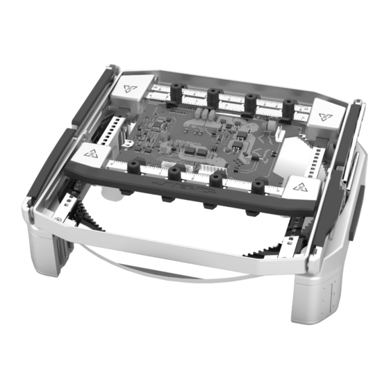
- Use a damp cloth when cleaning. Alcohol can only be used to clean the metal parts - Replace any defective or damaged piece. Use original JBC spare parts only. - Repairs should only be performed by a JBC authorized technical service. Sliding Guide Axes... - Page 12 Safety It is imperative to follow safety guidelines to prevent electric shock, injury, fire or explosion. - When using the support with a preheater unit, the temperature of accessible surfaces may remain high after the unit is turned off. Handle with care. - Be careful with the remains of liquid tin.
- Page 13 para manuales - color gris para manuales - color gris 200 mm 200 mm Notes 130 mm 130 mm 130 mm 130 mm 100 mm 100 mm 80 mm 80 mm 60 mm 60 mm 50 mm 50 mm 40 mm 40 mm...
- Page 14 Notes...
- Page 15 para manuales - color gris para manuales - color gris 200 mm 200 mm Notes 130 mm 130 mm 130 mm 130 mm 100 mm 100 mm 80 mm 80 mm 60 mm 60 mm 50 mm 50 mm 40 mm 40 mm...
-
Page 16: Specifications
11.02 x 11.02 x 6.49 in / 6.5 lb Complies with CE standards. ESD safe. Warranty JBC’s 2 year warranty covers this equipment against all manufacturing defects, including the replacement of defective parts and labour. Warranty does not cover product wear or misuse.
Need help?
Do you have a question about the PSS and is the answer not in the manual?
Questions and answers