Table of Contents
Advertisement
Quick Links
AUF750 Series Operation Manual
OP750.1.1.7ENG
ALIASONIC
®
Transit-Time Ultrasonic Flowmeter
Model AUF750 Series
Operation Manual
URL: http://www.alia-inc.com
Alia Group Inc.
113 Barksdale Professional Center, Newark, DE 19711, USA
E-mail: alia@alia-inc.com
TEL : +1 - 302 - 213 - 0106
FAX : +1 - 302 - 213 - 0107
OP750.1.1.7ENG
1
Advertisement
Table of Contents

Related Manuals for Alia AUF750 Series


Summary of Contents for Alia AUF750 Series
- Page 1 AUF750 Series Operation Manual OP750.1.1.7ENG ALIASONIC ® Transit-Time Ultrasonic Flowmeter Model AUF750 Series Operation Manual URL: http://www.alia-inc.com Alia Group Inc. 113 Barksdale Professional Center, Newark, DE 19711, USA E-mail: alia@alia-inc.com TEL : +1 - 302 - 213 - 0106 FAX : +1 - 302 - 213 - 0107...
-
Page 2: Table Of Contents
AUF750 Series Operation Manual OP750.1.1.7ENG Index 1. Introduction- - - - - - - - - - - - - - - - - - - - - - - - - - - - - - - - - - - - - - - - - - - - - - - - - - - - - - - - - - - 1.1 Preface - - - - - - - - - - - - - - - - - - - - - - - - - - - - - - - - - - - - - - - - - - - - - - - - - - - - - - - - - - -... - Page 3 AUF750 Series Operation Manual OP750.1.1.7ENG 3.10 Low Flow Cutoff- - - - - - - - - - - - - - - - - - - - - - - - - - - - - - - - - - - - - - - - - - - - - - - - - - - - 3.11 Zero Set Calibration - - - - - - - - - - - - - - - - - - - - - - - - - - - - - - - - - - - - - - - - - - - - - - - -...
-
Page 4: Introduction
1. Introduction 1.1 Preface Welcome to the AUF750 series ultrasonic flow meter that has been manufactured with the newest technologies and is equipped with more functions and advanced performance than our previous versions. The AUF750 Series flow meter incorporates the latest ICs manufactured from the famous semiconductor manufacturers like Philips, TI, Winbond, and Xilinx. -
Page 5: Applications
AUF750 Series Operation Manual OP750.1.1.7ENG Remarks: M -- Transit time of the ultrasonic signal -- Pipe Inside Diamete -- The angle between the ultrasonic signal and the flow θ -- No liquid movement the Fluid Sound Velocity -- Fluid Velocity... -
Page 6: Figures And Wiring Diagram
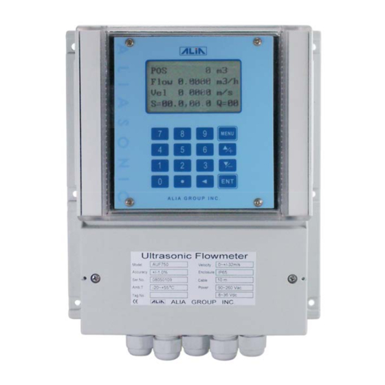
AUF750 Series Operation Manual OP750.1.1.7ENG 1.6 Figures and Wiring Diagram 205 mm 95 mm TOT 123456.78m3 FLOW 34.567m3/h 1.234m/s S=86.7, 87.8 Q =87.9 MENU ALIA GROUP INC . Ultrasonic Flowmeter Mo d e l A UF7 5 0 Ve l o ci ty... -
Page 7: Starting Installation And Measurement
AUF750 Series Operation Manual OP750.1.1.7ENG 2. Starting Installation and Measurement 2.1 Inspection prior to Installation nspection should be made before installing the AUF-750. Check to see if the spare parts are in accordance with the packing list. Make sure that there is no potential damage to the enclosure due to a loose screw or loose wire, which occurred during transportation. -
Page 8: Window Descriptions
AUF750 Series Operation Manual OP750.1.1.7ENG Generally, press ENT key first if operator wants to enter “modify” condition. If the “modify” is still not possible even after pressing the ENT key, it means that system is locked by a password. To “Unlock” it, select “Unlock”... -
Page 9: Transducer Wiring
AUF750 Series Operation Manual OP750.1.1.7ENG 2.8 Transducer Wiring Black Black Ultraonic Grease Photo 2.8.2 Silicone Flow direction Photo 2.8.3 Photo 2.8.1 Sensor Installation 1. Please clear the outside of the pipe. 2. Apply the Ultrasonic Grease on the sensor average, make sure there have no any air between sensor & pipe. -
Page 10: Z Method
AUF750 Series Operation Manual OP750.1.1.7ENG TRANSDUCER DOWNSTREAM TRANSDUCER UPSTREAM TRANSDUCER Flow direction Transducer spacing Flow direction UPSTREAM TRANSDUCER DOWNSTREAM TRANSDUCER Transducer spacing V Method Photo 2.12.1 2.13 Z Method The signal transmitted in a Z method installation has less attenuation than a signal transmitted with the V method. -
Page 11: Transducer Mounting Inspection
AUF750 Series Operation Manual OP750.1.1.7ENG 2.16 Transducer Mounting Inspection Check to see if the transducer is installed properly and if there is an accurate and strong enough ultrasonic signal to ensure proper operation and high reliability of the transducer. It can be confirmed by checking the detected signal strength, total transit time, delta time as well as transit time ratio. -
Page 12: Operating Instructions
AUF750 Series Operation Manual OP750.1.1.7ENG 3. Operating Instructions 3.1 System Normal Identification Press the MENU 0 8 keys. If the letter “*R”displays on the screen, it indicates system normal. If the letter “E” is read, it indicates that the current loop output is over ranged by 100%. This refers to the settings in Window M56. Enter a larger value in Window M56, and the letter “E”... -
Page 13: Low Flow Cutoff
AUF750 Series Operation Manual OP750.1.1.7ENG 3.9 Damping The damping function will stabilize the flow display. Essentially, it is a part of the signal filter. Enter a coefficient in Window M40. Increasing the coefficient increases the stability. However, the measurement displayed may be slightly delayed due to over damping. Logging too long may result in no response to real-time fluctuation, especially when flow rate fluctuates wildly. -
Page 14: 20Ma Current Loop Verification
AUF750 Series Operation Manual OP750.1.1.7ENG 3.14 4~20mA Current Loop Verification Possessing a current loop output exceeding an accuracy of 0.1%, the AUF-750 is programmable and configurable with multiple output modules such as 4 ~20mA or 0~20mA. Select in Window M54. For details,please refer to Chapter of Windows Display Explanations. -
Page 15: Oct Output
AUF750 Series Operation Manual OP750.1.1.7ENG Example 1: To program the relay output alarm, activated when flow rate exceeds 300~1000m 1. In Window M73, input 300; 2. In Window M74, input 1000; 3. In Window M79, select item 6: “6. Alarm #1 limit exceed”. -
Page 16: Analog Output Calibration
AUF750 Series Operation Manual OP750.1.1.7ENG 3.26 Analog Output Calibration Each flowmeter has been calibrated strictly before leaving factory. It is unnecessary to carry through this step except when the current value (detected while calibrating the current loop) displayed in Window M62 is not identical with the actual output current value. -
Page 17: Windows Display Explanations
AUF750 Series Operation Manual OP750.1.1.7ENG 4. Windows Display Explanations 4.1 Windows Display Codes Item Flow Totalizer Display Item Setup Options Item Calorimetry POS / NEG / NET Totalizer Network I DN Diagnoses POS / Flow Rate/Velocity System Lock Strength+Quality NEG / Flow Rate/ Velocity... -
Page 18: Display Explanation
AUF750 Series Operation Manual OP750.1.1.7ENG 4.2 Display explanation While reading this section, please compare it with the instrument in order to improve your understanding. MENU 0 0 + 6 m3 POS/NEG/NET/S,Q -2 m3 + 4 m3 Display POS Totalizer,NEG Totalizer ,NET Totalizer and S,Q Value. - Page 19 AUF750 Series Operation Manual OP750.1.1.7ENG M 11 MENU 1 1 Pipe Outer Diame Pipe Outside Diameter Enter the pipe outside diameter, or enter pipe circumference in Window M10. The pipe outside diameter must range from 15mm to 6000mm. Note: Enter either pipe outside diameter or pipe circumference.
- Page 20 STANDARD – S USER TYPE 8. STANDARD - HS STANDARD - B 9. STANDARD - HM **For Alia sensor you only need to choose : 0. STANDARD – M 2. STANDARD – S 6. STANDARD – L MENU 2 4...
- Page 21 AUF750 Series Operation Manual OP750.1.1.7ENG MENU 3 1 M 31 Flow Rate Units Options Flow Rate Units Select the flow rate units and time units. m3/h The following flow rate units are available: 0. CUBIC METERS 1. LITERS 2.(AMERICAN) GALLONS 3.
- Page 22 AUF750 Series Operation Manual OP750.1.1.7ENG If it is necessary to recover the factory default, press . ← keys after the above-mentioned,characters are displayed on the screen. MENU 3 8 M 38 Manual Totalizer Manual Totalizer Pre ENT When Ready Display the manual totalizer,Please press ENT to start,and press ENT again to stop.
- Page 23 AUF750 Series Operation Manual OP750.1.1.7ENG MENU 4 5 M 45 Scale Factor Scale Factor The scale factor is used to modify the measurement results. Factory default is 1. The user can enter a numerical value other than “1” according to calibration results.
- Page 24 AUF750 Series Operation Manual OP750.1.1.7ENG MENU 5 3 M 53 4-20mA electric current calibration CL Calibration This window can calibrate 4-20mA current, detail please check§3.30 Pre ENT When Rea MENU 5 4 Current Loop Mode Select M 54 Select the current loop mode. The following options are available: CL Mode Select 0.
- Page 25 AUF750 Series Operation Manual OP750.1.1.7ENG M 60 MENU 6 0 Date 08-08-08 Date and Time Settings Time 08:08:08 Date and time modifications. The format for setting time setting is 24 hours. Press ENT, wait until “>” appears, the modification can be made.
- Page 26 AUF750 Series Operation Manual OP750.1.1.7ENG M 71 MENU 7 1 LCD Contrast LCD contrast control This window can control LCD contrast. MENU 7 2 M 72 Working Timer Working Timer This window can display total working hours 00000008:08:08 They unit are:Hour, minute, second...
- Page 27 AUF750 Series Operation Manual OP750.1.1.7ENG ME NU 7 9 M 79 Relay Output Setup Relay Output Set Set up the relay output signal options. The relay is single-pole and constant-on Not Using for external instrument controls. The following options are available: 0.
- Page 28 AUF750 Series Operation Manual OP750.1.1.7ENG MENU 8 6 M 86 Heat Capacity Spec Heat Select Select the following 2 kinds of specific heat value: 0. Standard Specific Heat 1. Fixed Specific Heat. Generally specific heat of water is 0.0041868GJ/M3℃. MENU 8 7...
- Page 29 AUF750 Series Operation Manual OP750.1.1.7ENG MENU 9 4 M 94 Reynolds Number Reynolds Number and Factor 0.0000 0.7500 Display the Reynolds number that is calculated by the AUF750 and the factor that is set currently by the flowmeter. Normally this scaling factor is the average of the line and surface velocity factor inside the pipe.
-
Page 30: Error Diagnoses
AUF750 Series Operation Manual OP750.1.1.7ENG 5. Error Diagnoses The AUF750 ultrasonic flowmeter has advanced self-diagnostics functions and displays any errors in the upper right corner of the LCD via definite codes in a date/time order. Hardware error diagnostics are usually performed upon each power on. - Page 31 AUF750 Series Operation Manual OP750.1.1.7ENG Table 2. Error codes and solutions (during operation) Code M08 Display Cause Solution System Normal * System normal No errors SCPU Fatal Error * Hardware defect * Contact the factory Signal Not Detected *Signal not detected.
-
Page 32: Frequently Asked Questions And Answers
AUF750 Series Operation Manual OP750.1.1.7ENG 6. Frequently Asked Questions and Answers Q: New pipe, high quality material, and all installation requirements met: why still no signal detected? A: Check pipe parameter settings, installation method and wiring connections. Confirm if the coupling compound is applied adequately, the pipe is full of liquid, transducer spacing agrees with the screen readings and the transducers are installed in the right direction.
Need help?
Do you have a question about the AUF750 Series and is the answer not in the manual?
Questions and answers