Table of Contents
Advertisement
Quick Links
Advertisement
Table of Contents

Related Manuals for Alia AMC2100 Series


Summary of Contents for Alia AMC2100 Series
- Page 1 ALIA TECHNOLOGY LLC...
-
Page 2: Table Of Contents
Index 1. Sensor ----------------------------------------------------------------------------------------------------------------------------------2 1.1 AMF900 Flange Type-------------------------------------------------------------------------------------------------------2 1.2 AMF500 Wafer Type --------------------------------------------------------------------------------------------------------3 1.3 AMF301 Installation ---------------------------------------------------------------------------------------------------------3 1.4 AMF500 Installation ---------------------------------------------------------------------------------------------------------3 1.5 AMF601 Installation ---------------------------------------------------------------------------------------------------------4 1.6 AMF900 Installation ---------------------------------------------------------------------------------------------------------4 2. Installation------------------------------------------------------------------------------------------------------------------------------5 2.1 Install position-----------------------------------------------------------------------------------------------------------------5 2.2 Remove the interference of magnetic field ----------------------------------------------------------------------------5 2.3 Straight tube length----------------------------------------------------------------------------------------------------------5 2.4 Install method -----------------------------------------------------------------------------------------------------------------5 3. -
Page 3: Sensor
1. Sensor EM Flowmeter composed by sensor and Converter, be compact version or separate version, there are several specification of sensor as follow: 1.1 AMF900 Flange Type Size: 10Amm ~ 2000mm (3/8A” ~ 80”) Liner : Neoprene Polyurethane PTFE Protection : IP68 Max.Temp.:180 Deg. -
Page 4: Amf500 Wafer Type
1.2 AMF500 Wafer Type Size: 25mm ~ 200mm (1” ~ 8”) Liner: FEP/PTFE Protection: IP68 Max.Temp.: 180 Deg. C Installation: Wafer Size Dimensions (mm) Inch 1" 1-1/4" 1-1/2" 2" 2-1/2" 3" 4" 5" 6" 8" 1.3 AMF301 Installation 1.4 AMF500 Installation Tie-rod Packing Flange... -
Page 5: Amf601 Installation
1.5 AMF601 Installation 1.6 AMF900 Installation Installation Note: 1) The pipe flange should be welded well before installing flowmeter. It's not allowed to weld flange after flowmeter is installed. And welding part of pipe flange should be flat, having no sharp residue. Otherwise liner will be damaged. After flowmeter is installed, if other places in pipe needs to be welded, flowmeter's power must be shut down. -
Page 6: Installation
2. Installation When you design the tube, please consider following items: 2.1 Install position Please avoid the sunlight when you install the flowmeter, the ambient temperature between-25~60 Deg.C will be great. 2.2 Remove the interference of magnetic field Please DO NOT install flowmeter near motor-driven machine, transformer, frequency transformer etc. for it will cause interference of magnetic field.. - Page 7 d. Electrode position should parallel with ground EM Flowmeter installed by horizontal or slanting the electrode position(A.B) should match the 2 side( right/left)of tube, converter(wiring box)should be top of the tube. Exhaust valve >300mm Horizontal install, the electrode position A.B should on the right and left side. e.
-
Page 8: Converter Amc2100 Operate Manual
3. Converter AMC2100 Operate Manual 3.1 Converter AMC2100 Operate Manual 3.1.1 Power and signal output connected line(compact and separate model) Open the 4 screws of the converter, and you can see terminal, decide if you need to connect according to your needs. 20mA output 2.4 20m output 3 Pulse... -
Page 9: Separate Wiring
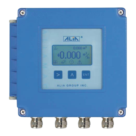
3.1.2 Separate Wiring Converter AMC2100 Series A B C Electorde Coil Sensor AMF300 AMF500 AMF601 AMF900 A B C Series 3.1.3 AMC2100 Panel deploy 123.456 m3 +0.000 m3/h Button Normal status function Parameter setting status function Name Sign Login parameter setting level Save presently settled parameter. -
Page 10: Survey Mode Setting
3.2 Survey mode setting Flowmeter will enter to normal mode when electrified, every line has several choice as follow: Position Display Unit sign Unit Description Totalizer Line 1 L, M3, G , kg, T,ml Totalizer+ Totalizer- Velocity When reverse flow, it will show”- ”... -
Page 11: Auto Zero Adjustment
3.5 Auto zero Adjustment When the tube are full pipe, and no flow, flowmeter still show the flowrate, then you could use Auto Zero adjustment to adjust your flowmeter to Zero, the method as follow: 123.456 m3 In the normal display, press button for 5 seconds, then it will go to next setting +0.1234 m3/h... -
Page 12: Operate Flow Chart
3.7 Operate flow chart 123.456 m3 +0.0000 m3/h OPERATIONS ZERO Password 0000 Empty Detect Empty Limit(%) Language PV Units Communication HART Address MODBUS Type Switch Func Baudrate Liter/Pulse Freq of URV (Hz) Data Bit Pulse Width Alarm Select Parity Pulse Level UPPER-Alarm Stop Bit Low Cutoff(%fs) - Page 13 Password Password **** 1111 Sensor NO. Sensor NO. Size (mm) Size (mm) Sensor Factor Sensor Factor Revise Revise Speed Revise Output Check Output Check Loop Test Empty Tube Trim Pulse Test Full Tube Trim Coil Test Restore Shipping Empty Tube Trim Convertor NO.
-
Page 14: User Operate Description
3.8 User operate description 123.456 m3 In the normal display, press button for 5 seconds, then it will go to next setting +0.0000 m3/h OPERATIONS In this setting, Press button till you selected SET ZERO Password Password login window Input the password 0000 Password: 0000 Language... - Page 15 Pulse Level Pulse Level Press to selected Pulse Level Active L Active H Cutoff (%fs) Function for cutoff the low flowrate Press button to move, press button to change the Value Setting Range: 0.0% ~ 9.9% Damping (s) The flowrate response time setting, Press button to move, Press button the Value...
- Page 16 Comm Communication Press button to select if need to use communication function Please read page 17 HART Address MODBUS Type MODBUS Mode Press button to select MODBUS mode ASCII RS485 Speed Baudrate 1200 2400 Press button to select communication speed. 4800 9600 19200...
- Page 17 HART operate description HART Address HART Address Press button to select HART Address DATE (yy-mm-dd) Date Setting Press button to move, Press button to change the digit. 08-01-10 TIME (hh:mm:ss) Time Setting Press button to move, Press button to change the digit. Pls press button for 5 seconds, then it will go back to the normal display.
-
Page 18: System Mode
3.9 System Mode OPERATIONS In the normal display, press button for 5 seconds, then it will go to next setting In this setting, Press button till you selected SET ZERO Password Password login window Input the system password: 1111 Password: 1111 Sensor NO. - Page 19 Empty Tube Trim Empty Tube Trim Press to choose whether to Empty Tube Trim or not, or input empty tube frequency value. Choose NO to skip to Full Tube Trim, choose YES to conduct Empty Tube Trim. Keyin If there is empty tube empirical value, you can choose Keyin to modify empty tube frequency value. Otherwise it is not recommended to modify empty tube frequency value.
-
Page 20: Advance Mode
3.10 Advance Mode OPERATIONS In the normal display, press button for 5 seconds, then it will go to next setting In this setting, Press button till you selected SET ZERO Password Password login window Input the system password: **** Password: * * * * Sensor NO. - Page 21 Empty Tube Trim Empty Tube Trim Press to choose whether to Empty Tube Trim or not, or input empty tube frequency value. Choose NO to skip to Full Tube Trim, choose YES to conduct Empty Tube Trim. Keyin If there is empty tube empirical value, you can choose Keyin to modify empty tube frequency value. Otherwise it is not recommended to modify empty tube frequency value.
-
Page 22: Points Reviseion
Revise_1 ps: normally flowmeter accuracy it’s during standard accuracy, only if it’s necessary, please do not adjust any accuracy curve or you can ask Alia professional engineer to adjust with you 1.00000 Speed_2 m/s Example 1: size :50 mm(2”), Calibration flowrate are:0.5 M3/Hr, 1 M3/hr, 2 M3/Hr, 4 M3/hr, 00.500... - Page 23 Example 2: Size :500 mm (20”), Calibration one point flowrate to 4000 m 3 /h Revise_5 Supposed the actual flowrate was 4000 m 3 /h,the actual speed was 5.66 m/s, display 4012 m 3 /h, Velocity 5.677 m/s. 1.00000 New Revise=4000/4012=0.997 Flow Velocity 5.66 m/s during Revise_5 (4 m/s) and Revise_6 (6 m/s),so you can set as follow: Speed_5=5.66, Revise_5=0.997, Speed_6 and Revise_6 not change...
-
Page 24: Batch Control
3.12 Batch Control 123.456 m3 In the normal display, press button for 5 seconds, then it will go to next setting +0.0000 m3/h OPERATIONS In this setting, Press button till you selected SET ZERO Password Password login window Input the password 0000 Password: 0000 Language... - Page 25 123.456 m3 In general display, Press button and select ,make sure enter batch control window +0.0000 m3/h Batch Control Batch Control Press button to SET AUTO MANUAL EXIT Batch Value(m3) Batch Value(m3) Press button to move, press button to change the Value 1.00000 Batch Control...
-
Page 26: Common Alarm Code Indication
4. Common Alarm Code Indication AMC2100 Alarm Table Code Contents Meaning Solution OV. Flow Over range Increase range OV. Flow Exceeding AD value of flowrate Slow fluid velocity Over range Increase range OV. Flow Exceeding AD value of flowrate Slow fluid velocity OV. - Page 27 Tel: +1-213-533-4139 Fax: +1-213-223-2317 URL: www alia inc com Email: alia @alia inc com 633 W. 5th Street, 26th Floor, Los Angeles, CA 90071, USA...
Need help?
Do you have a question about the AMC2100 Series and is the answer not in the manual?
Questions and answers