Table of Contents
Advertisement
Quick Links
AUF760 Series Operation Manual
OP760.1.1.7ENG
ALIASONIC
®
Transit-Time Ultrasonic Flowmeter
Model AUF760 Series
Operation Manual
URL: http://www.alia-inc.com
Alia Group Inc.
113 Barksdale Professional Center, Newark, DE 19711, USA
E-mail: alia@alia-inc.com
TEL : +1 - 302 - 213 - 0106
FAX : +1 - 302 - 213 - 0107
OP760.1.1.7ENG
1
Advertisement
Table of Contents

Related Manuals for Alia AUF760 Series


Summary of Contents for Alia AUF760 Series
- Page 1 AUF760 Series Operation Manual OP760.1.1.7ENG ALIASONIC ® Transit-Time Ultrasonic Flowmeter Model AUF760 Series Operation Manual URL: http://www.alia-inc.com Alia Group Inc. 113 Barksdale Professional Center, Newark, DE 19711, USA E-mail: alia@alia-inc.com TEL : +1 - 302 - 213 - 0106 FAX : +1 - 302 - 213 - 0107...
-
Page 2: Table Of Contents
AUF760 Series Operation Manual OP760.1.1.7ENG Index 1. Introduction- - - - - - - - - - - - - - - - - - - - - - - - - - - - - - - - - - - - - - - - - - - - - - - - - - - - - - - - - - - 1.1 Preface - - - - - - - - - - - - - - - - - - - - - - - - - - - - - - - - - - - - - - - - - - - - - - - - - - - - - - - - - - -... - Page 3 AUF760 Series Operation Manual OP760.1.1.7ENG 3.10 Low Flow Cutoff- - - - - - - - - - - - - - - - - - - - - - - - - - - - - - - - - - - - - - - - - - - - - - - - - - - - 3.11 Zero Set Calibration - - - - - - - - - - - - - - - - - - - - - - - - - - - - - - - - - - - - - - - - - - - - - - - -...
-
Page 4: Introduction
1. Introduction 1.1 Preface Welcome to the AUF760 series ultrasonic flow meter that has been manufactured with the newest technologies and is equipped with more functions and advanced performance than our previous versions. The AUF760 Series flow meter incorporates the latest ICs manufactured from the famous semiconductor manufacturers like Philips, TI, Winbond, and Xilinx. -
Page 5: Applications
AUF760 Series Operation Manual OP760.1.1.7ENG Remarks: M -- Transit time of the ultrasonic signal -- Pipe Inside Diamete -- The angle between the ultrasonic signal and the flow θ -- No liquid movement the Fluid Sound Velocity -- Fluid Velocity... -
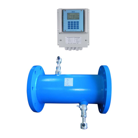
Page 6: Figures And Wiring Diagram
AUF760 Series Operation Manual OP760.1.1.7ENG 1.6 Figures and Wiring Diagram 205 mm 95 mm TOT 123456.78m3 FLOW 34.567m3/h 1.234m/s S=86.7, 87.8 Q =87.9 MENU ALIA GROUP INC . Ultrasonic Flowmeter Mo d e l A UF7 5 0 Ve l o ci ty... -
Page 7: Starting Installation And Measurement
AUF760 Series Operation Manual OP760.1.1.7ENG 2. Starting Installation and Measurement 2.1 Inspection prior to Installation nspection should be made before installing the AUF-760. Check to see if the spare parts are in accordance with the packing list. Make sure that there is no potential damage to the enclosure due to a loose screw or loose wire, which occurred during transportation. -
Page 8: Window Descriptions
AUF760 Series Operation Manual OP760.1.1.7ENG Generally, press ENT key first if operator wants to enter “modify” condition. If the “modify” is still not possible even after pressing the ENT key, it means that system is locked by a password. To “Unlock” it, select “Unlock”... -
Page 9: Transducer Wiring
AUF760 Series Operation Manual OP760.1.1.7ENG 2.8 Transducer Wiring Black Black Transducer Transducer Spacing Photo 2.8.1 (Front view ) 2.9 Installation ELBOW90 T-Tube Grove Value Reducer... -
Page 10: Transducer Spacing
AUF760 Series Operation Manual OP760.1.1.7ENG 2.10 Transducer spacing Please enter window M25 for checking the installation space of insertion transducer 2.11 Transducer Mounting Methods Use Z methods for transducer installation,Please enter Window M23 for checking the installation meathod. 2.12 Z Method (not commonly used) Z method installation has less attenuation, because it utilizes a directly transmitted (rather than reflected) signal which transverses the liquid only once. -
Page 11: Install Question
AUF760 Series Operation Manual OP760.1.1.7ENG 2.17 Install Question 1. Pipe parameters entered must be accurate; otherwise the flowmeter will not work properly. 2. During the installation, apply enough coupling compounds in order to stick the transducer onto the pipe wall. While checking the signal strength and Q value, move the transducer slowly around the mounting site until the strongest signal and maximum Q value can be obtained. -
Page 12: Operating Instructions
AUF760 Series Operation Manual OP760.1.1.7ENG 3. Operating Instructions 3.1 System Normal Identification Press the MENU 0 8 keys. If the letter “*R”displays on the screen, it indicates system normal. If the letter “E” is read, it indicates that the current loop output is over ranged by 100%. This refers to the settings in Window M56. Enter a larger value in Window M56, and the letter “E”... -
Page 13: Damping
AUF760 Series Operation Manual OP760.1.1.7ENG 3.9 Damping The damping function will stabilize the flow display. Essentially, it is a part of the signal filter. Enter a coefficient in Window M40. Increasing the coefficient increases the stability. However, the measurement displayed may be slightly delayed due to over damping. Logging too long may result in no response to real-time fluctuation, especially when flow rate fluctuates wildly. -
Page 14: 20Ma Current Loop Verification
AUF760 Series Operation Manual OP760.1.1.7ENG 3.14 4~20mA Current Loop Verification Possessing a current loop output exceeding an accuracy of 0.1%, the AUF-760 is programmable and configurable with multiple output modules such as 4 ~20mA or 0~20mA. Select in Window M54. For details,please refer to Chapter of Windows Display Explanations. -
Page 15: Oct Output
AUF760 Series Operation Manual OP760.1.1.7ENG Example 1: To program the relay output alarm, activated when flow rate exceeds 300~1000m 1. In Window M73, input 300; 2. In Window M74, input 1000; 3. In Window M79, select item 6: “6. Alarm #1 limit exceed”. -
Page 16: Analog Output Calibration
AUF760 Series Operation Manual OP760.1.1.7ENG 3.26 Analog Output Calibration Each flowmeter has been calibrated strictly before leaving factory. It is unnecessary to carry through this step except when the current value (detected while calibrating the current loop) displayed in Window M62 is not identical with the actual output current value. -
Page 17: Windows Display Explanations
AUF760 Series Operation Manual OP760.1.1.7ENG 4. Windows Display Explanations 4.1 Windows Display Codes Item Flow Totalizer Display Item Setup Options Item Calorimetry POS / NEG / NET Totalizer Network I DN Diagnoses POS / Flow Rate/Velocity System Lock Strength+Quality NEG / Flow Rate/ Velocity... -
Page 18: Display Explanation
AUF760 Series Operation Manual OP760.1.1.7ENG 4.2 Display explanation While reading this section, please compare it with the instrument in order to improve your understanding. MENU 0 0 + 6 m3 POS/NEG/NET/S,Q -2 m3 + 4 m3 Display POS Totalizer,NEG Totalizer ,NET Totalizer and S,Q Value. - Page 19 AUF760 Series Operation Manual OP760.1.1.7ENG M 11 MENU 1 1 Pipe Outer Diame Pipe Outside Diameter Original factory rectified factor,not professional,please don’t change it. M 12 MENU 1 2 Pipe Wall Thickn Pipe Wall Thickness Original factory rectified factor,not professional,please don’t change it.
- Page 20 AUF760 Series Operation Manual OP760.1.1.7ENG M 25 MENU 2 5 Transducer Spaci 72.8337 mm TRANSDUCER SPACING Transducer Spacing (this value is CALCULATED by the AUF 760) The operator must mount the transducer according to the transducer spacing displayed (be sure that the transducer spacing must be measured precisely during installation).
- Page 21 AUF760 Series Operation Manual OP760.1.1.7ENG MENU 3 3 M 33 Totalizer Multiplier Options Totalizer Multiplier The totalizer multiplier acts as the function to increase the totalizer indicating 3. X 1 range. Meanwhile, the totalizer multiplier can be applied to the positive totalizer, negative totalizer and net totalizer at the same time.
- Page 22 AUF760 Series Operation Manual OP760.1.1.7ENG M 41 MENU 4 1 Low Flow Cutoff Low Flow Cutoff Value 0.03 m/s The Low flow cutoff may be used in order to make the system display a “0” value at lower and smaller flows to avoid incorrect totalization. For instance, if the cutoff value is set as “0.03”, system will take all the measured flow values of ±0.03 as “0”.
- Page 23 AUF760 Series Operation Manual OP760.1.1.7ENG MENU 4 9 M 49 Communication function test Communication Te MENU 5 0 M 50 Logger Option Logger setup This window can set up open or close the print function and can also set up the specific time to print.enter ENT, use up and down arrowhead to select”ON”or”OFF”.”OFF”means close the print function.When you...
- Page 24 AUF760 Series Operation Manual OP760.1.1.7ENG value of the actual flow; therefore, both F0mA(or F4mA)and F20mA must be selected as positive flow values. In mode 0-4-20mA, F0mA must be select as a negative value and F20mA as a positive value. Furthermore, in mode 4- 20mA, the output current is indicated as velocity.
- Page 25 AUF760 Series Operation Manual OP760.1.1.7ENG MENU 6 4 AI2 Value Range M 64 This window can setup 4-20 mA value for Temperature or AI2 Value Range Pressure transmitter range. 10 - 100 Example:0 – 100 Means 4mA corresponded value is: 0...
- Page 26 AUF760 Series Operation Manual OP760.1.1.7ENG ME NU 7 6 M 76 Alarm #2 High Value Alarm #2 High Val Enter the alarm High value. Both relevant alarms are turned on in Windows M78 1440 m3/h and M79; any measured flow, which is lower than the low value, will activate the alarm in the OCT hardware or relay output signal.
- Page 27 AUF760 Series Operation Manual OP760.1.1.7ENG ME NU 8 2 M 82 YEARLY / MONTHLY / DAILY TOTALIZER Date Totalizer Display yearly, monthly, daily totalizer 0. Day DAILY 1. MONTHLY 2. YEARLY In this window, it is possible to review the historical flow data totalizer for any day for the last 64 days, any month for last 64 months and any year for last 5 years.
- Page 28 AUF760 Series Operation Manual OP760.1.1.7ENG M 89 MENU 8 9 Reset Energy Tot Reset Energy Totalizer Select “YES” to reset Energy Totalizer value. MENU 9 0 M 90 Strenth+Quality Signal Strength and Signal Quality Q=81.40,81.400Q=83.2 Display the measured signal strength and signal quality Q value upstream and downstream.Signal strength is indicated from 00.0~99.9.
- Page 29 AUF760 Series Operation Manual OP760.1.1.7ENG MENU + 2 M +2 Last Off Time Last Off Time Date 08-08-08 Display last off time Time 08:08:08 MENU + 3 M +3 Last Flow Rate Last Flow Rate 0 m3/h Display last flow rate...
-
Page 30: Error Diagnoses
AUF760 Series Operation Manual OP760.1.1.7ENG 5. Error Diagnoses The AUF760 ultrasonic flowmeter has advanced self-diagnostics functions and displays any errors in the upper right corner of the LCD via definite codes in a date/time order. Hardware error diagnostics are usually performed upon each power on. - Page 31 AUF760 Series Operation Manual OP760.1.1.7ENG Table 2. Error codes and solutions (during operation) Code M08 Display Cause Solution System Normal * System normal No errors SCPU Fatal Error * Hardware defect * Contact the factory Signal Not Detected *Signal not detected.
-
Page 32: Frequently Asked Questions And Answers
AUF760 Series Operation Manual OP760.1.1.7ENG 6. Frequently Asked Questions and Answers Q: New pipe, high quality material, and all installation requirements met: why still no signal detected? A: Check pipe parameter settings, installation method and wiring connections. Confirm if the coupling compound is applied adequately, the pipe is full of liquid, transducer spacing agrees with the screen readings and the transducers are installed in the right direction.
Need help?
Do you have a question about the AUF760 Series and is the answer not in the manual?
Questions and answers