Table of Contents
Advertisement
AVF7000 Operation Manual
OP7000.1.1.7.R12ENG
A L I A V T X
®
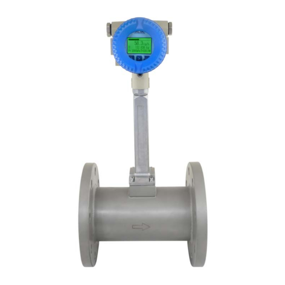
Vortex Flowmeter
AVF7000 Series
Operation Manual
ALIA TECHNOLOGY LLC
URL: http://www.alia-inc.com
633 W. 5th Street, 26th Floor, Los Angeles, CA 90071, USA
E-mail: alia@alia-inc.com
TEL : +1 - 213 - 533 - 4139
FAX : +1 - 213 - 223 - 2317
OP7000.1.1.7.R12ENG
1
Advertisement
Table of Contents

Subscribe to Our Youtube Channel
Related Manuals for Alia ALIAVTX AVF7000 Series


Summary of Contents for Alia ALIAVTX AVF7000 Series
- Page 1 A L I A V T X ® Vortex Flowmeter AVF7000 Series Operation Manual ALIA TECHNOLOGY LLC URL: http://www.alia-inc.com 633 W. 5th Street, 26th Floor, Los Angeles, CA 90071, USA E-mail: alia@alia-inc.com TEL : +1 - 213 - 533 - 4139 FAX : +1 - 213 - 223 - 2317 OP7000.1.1.7.R12ENG...
-
Page 2: Table Of Contents
AVF7000 Operation Manual OP7000.1.1.7.R12ENG Index 1. Flowmeter Check --------------------------------------------------------------------------------------------------------------------3 2. Product Overview --------------------------------------------------------------------------------------------------------------------3 3. Working Principle --------------------------------------------------------------------------------------------------------------------3 4. Specifications -------------------------------------------------------------------------------------------------------------------------4 5. Dimensions ----------------------------------------------------------------------------------------------------------------------------5 6. Installation------------------------------------------------------------------------------------------------------------------------------6 7. Wiring Diagram -----------------------------------------------------------------------------------------------------------------------8 7.1 With 4-20mA(2 wire) or Scale pulse,but without Temp./ Pressure Compensation--------------------------8 7.2 With RS485 Communication,but without Temp./ Pressure Compensation -----------------------------------8 7.3 With Temp./ Pressure Compensation,and 4-20mA(2 wire) or Scale pulse output --------------------------9 7.4 With Temp./ Pressure Compensation,and RS485 Communication------------------------------------------- 10... -
Page 3: Flowmeter Check
3. Working Principle ALIA AVF7000 is newly stress-type flowmeter that’s based on von Karman effect. It’s made up of a whole body whose internal diameter and nominal diameter are the same and a triangular bluff body inside. Flow will alternately generate vortices when passing by a bluff body. -
Page 4: Specifications
AVF7000 Operation Manual OP7000.1.1.7.R12ENG 4. Specifications Size (mm) : 15, 20, 25, 32, 40, 65, 80, 100, 125, 150, Protection Class : IP 65. 200, 250, 300, 350, 400, 450, 500 mm Explosion Proof Exd IIC T6 Measuring Range : Steam - 1.6 to 540,000 Kg/Hr Intrinsically safe Exia IIC T4 Gas - 3 to4 6,000 m3/Hr Local Display... -
Page 5: Dimensions
AVF7000 Operation Manual OP7000.1.1.7.R12ENG 5. Dimensions Normal Size Inch 1/2" 3/4" 1" 1-1/4" 1-1/2" 2" 2-1/2" 3" 4" 5" 6" 8" 10" 12" 14" 16" 18" 20" Note: L5= reduced L4 + pipe diameter before reducing (Example:DN200mm reduce DN150mm , L5 = 400mm + 200mm = 600mm 1 5 2 m 3 h 1 5 2... -
Page 6: Installation
AVF7000 Operation Manual OP7000.1.1.7.R12ENG 6. Installation Installation position of Vortex Flowmeter is very important. It concerns measuring accuracy. Please leave more space of straight pipe in upstream and downstream as best as you can. If not permitted, please install as 2/3 of total straight pipe length on the upstream and 1/3 on downstream. - Page 7 AVF7000 Operation Manual OP7000.1.1.7.R12ENG ● Grounding Good grounding is highly demanded so as to avoid signal interference. Please see below pictures, all you need to do is to ground the displayer. And the sensor grounding is unnecessary. Grounding place is like stairs and railing. To define whether vortex is well grounded initially, user need to check whether frequency is 50HZ or 60HZ or not.
-
Page 8: Wiring Diagram
AVF7000 Operation Manual OP7000.1.1.7.R12ENG 7. Wiring Diagram Cable should be equipped as 2-core AVPV2*0.5mm2 or 3-core AVPV3*0.5mm2. Connecting terminals should be firm and tight. Meanwhile, shielding cable must be properly connected to the housing of amplifier. 7.1 With 4-20mA(2 wire) or Scale pulse,but without Temp./ Pressure Compensation 4-20mA and Scale Pulse 4-20mA (2 wire) output Output... -
Page 9: With Temp./ Pressure Compensation,And 4-20Ma(2 Wire) Or Scale Pulse Output
AVF7000 Operation Manual OP7000.1.1.7.R12ENG 7.3 With Temp./ Pressure Compensation,and 4-20mA(2 wire) or Scale pulse output 4-20mA and Scale Pulse Output I- A+ 1 5kohm 12 32 VDC Pulse Power Supply Output Sensor Input 4-20 mA Output Pulse Output Temperature Pressure 1 5KOhm 4 20mA 2 wire Current... -
Page 10: With Temp./ Pressure Compensation,And Rs485 Communication
AVF7000 Operation Manual OP7000.1.1.7.R12ENG 7.4 With Temp./ Pressure Compensation,and RS485 Communication I+ I- A+ A- Sensor Input 12-32 VDC Power supply RS485 Communication Temperature Pressure 12 32VDC Voltage Current RS485 + RS485 - Input Outout Power Supply Pressure Sensor PT1000 4 Wire... -
Page 11: Separation Board
AVF7000 Operation Manual OP7000.1.1.7.R12ENG 7.5 Separation board Note: The terminals S1+, S2+ are signal ports of vortex sensor. Terminal Cable color Sensor blue Pressure sensor black yellow white Temperature sensor orange Vortex sensor orange... -
Page 12: Panel Display
AVF7000 Operation Manual OP7000.1.1.7.R12ENG 8. Panel Display 10 3m3 h 9. Function 9.1 Button Function Button Function Setting SE T SE T Press shortly (1s) to enter menu settings or exit settings. Move Press shortly (1s) to shift to page down or move digit position when set parameters. Press shortly (1s) to shift to page up or increase value by “1”... -
Page 13: Field Application
AVF7000 Operation Manual OP7000.1.1.7.R12ENG 9.3 Field Application Two situations will frequently happen at site: A. No flow, it displays value. B. Flow, it displays zero. Reasons for problem A: vortex get interfered by outside environment, keeping receiving interference signals. In the picture below, interference signal is more than vortex’s threshold value. -
Page 14: Parameter Operation Chart
AVF7000 Operation Manual OP7000.1.1.7.R12ENG 10. Parameter Operation Chart 10.5 m3/h 20.0 m3 P=12.5Kpa T=20.0℃ SE T SE T Contrast Protection Min Alarm(%) Max Alarm(%) Meter Size Flow Mode Unit Range 100% Density(Kg/m3) Gauge Pre(Kpa) CODE SE T SE T K-Factor Temperature(℃) PV Cutoff (%) Total Overflow... - Page 15 AVF7000 Operation Manual OP7000.1.1.7.R12ENG 10.5 m3/h 20.0 m3 P=12.5Kpa T=20.0℃ CODE Password ## Password ## Password ## Password ## 4mA Trim Frequency Factor K-Factor Trim F1 Signal Monitor SE T SE T 20mA Trim CODE K-Factor Trim Y1 Meter Size SE T SE T SE T...
- Page 16 AVF7000 Operation Manual OP7000.1.1.7.R12ENG 10.5 m3/h 20.0 m3 P=12.5Kpa T=20.0℃ CODE Password ## Password ## Password ## Password ## AMP. Channel Work Mode Modbus Addr Temp. Measure SE T SE T SE T SE T CODE CODE Modbus Baud Pressure Measure SE T SE T SE T...
-
Page 17: Parameter Settings
AVF7000 Operation Manual OP7000.1.1.7.R12ENG 11. Parameter Settings 11.1 Basic Settings Normal Display 10.5 m3/h This interface shows flow rate and totalizer. 20.0 m3 SE T SE T Press to enter next setting interface. SE T Contrast Contrast Set the contrast, 1-5 are optional. The larger the number, the deeper the font color(default is 3). Set keys. - Page 18 AVF7000 Operation Manual OP7000.1.1.7.R12ENG Fluid Density Density(kg/m3) Set by keys. Gas density (unit: kg/m3); liquid density (unit: g/cm3) 1.025 Press to enter next setting interface. Gas Pressure (gauge pressure) Gauge pre.(Kpa) Set by keys. This is used for inputting pressure (unit: Kpa) manually (in Pressure 1000.00 Measure window).
- Page 19 AVF7000 Operation Manual OP7000.1.1.7.R12ENG K-Factor K-Factor Read-only window. Check K-factor. 9100.00 Press to back to normal display interface. Password Code Set by keys. Enter advanced settings by password. Press to return parameter 00000 protection interface. Press to back to normal display interface. SE T 10.5 m3/h 20.0 m3...
-
Page 20: Advanced Parameter Settings
Low Flow Limit Set by keys. Theoretical min. flow rate, this parameter does not affect the measurement, 35.000m3/h for reference only. Do not change it (if necessary, please contact ALIA). Press to enter next setting interface. High Flow Limit High Flow Limit Set by keys. -
Page 21: Output 4-20Ma Current Calibration
AVF7000 Operation Manual OP7000.1.1.7.R12ENG Pulse Factor Pulse Factor Press to select unit for pulse factor. Optional unit: t, kg, Nm3, m3, Scf, cf, USG, UKG, bbl, 9100.00 Ib. If select kg, the value means pulse/kg. Others apply the same. Press to return to signal strength and to password interface. -
Page 22: Points Linear Calibration
AVF7000 Operation Manual OP7000.1.1.7.R12ENG 11.4 5 Points linear Calibration Password Code Set by keys. Enter password 00060 then press long for 3s to enter revision settings. 00060 Non-engineer is not suggested to operate this, otherwise output accuracy of 4~20mA will be changed. -
Page 23: Amplification Gain Settings
Code Set by keys. Enter password XXXXX then press long for 3s to enter temperature/ 00000 pressure calibration settings (If necessary, please contact ALIA). Temperature Input Mode Temp.Measure There are 2 options: Manual and Auto. Manual mode, achieving temperature/pressure Auto compensation with setting value in window Temperature. - Page 24 Unit: KPa. If pressure is auto measuring, and displaying pressure is 0.00kpa inaccurate, you can input actual pressure in this window to achieve pressure shift directly. Do not change it (if necessary, please contact ALIA). Press twice to return to normal display interface. 10.5 m3/h...
-
Page 25: Modbus Communication Settings
AVF7000 Operation Manual OP7000.1.1.7.R12ENG 12. Modbus Communication Settings Mode: standard MODBUS-RTU. Details: Modbus: MODBUS-RTU mode Baudrate: 9600bps Serial data mode: Parity: None Databit: 8 Stopbit: 1 Communication address: 01 Password Code Press to enter password 00090. Hold for 3s to enter MODBUS settings. 00090 Communication Address Modbus Addr... -
Page 26: Commonly Seen Problems
③ If measuring medium is steam, please make sure actual temperature&pressure parameters are conformed with those inside circuit board. ④ Circuit board or sensor is faulted. Please send them back to ALIA for repair. 3. Vortex’s flow rate is unstable.
Need help?
Do you have a question about the ALIAVTX AVF7000 Series and is the answer not in the manual?
Questions and answers