Denon PMA-A100 - INTEGRATED AMPLIFIER Manual
- Service manual (53 pages) ,
- Owner's manual (16 pages) ,
- Owner's manual (16 pages)
Advertisement
Getting Started
Thank you for purchasing this DENON product. To ensure proper operation, please read this owner's manual carefully before using the product.
After reading the manual, be sure to keep it for future reference.
Main Features
- UHC [Ultra High Current]-MOS single push-pull circuit installed to simulta neously achieve bo th "subtlety" and "powerfulness"
Use of the minimum number of amplifier elements with between 3 and 10 times the normal power capacity produces a combination of both detailed expression and high power. From the pianissimo tones of a soloist emerging softly from silence to the hall-shaking power of a full orchestra, the artist's emotion is reproduced with exceptional balance. - Direct Mechanical Ground construction that suppresses vibration
The vibration-resistant construction has been redesigned to fully eliminate the impact of vibration on sound quality. To enhance transparency and the sound image, measures have been implemented in regard to the installation and positioning of various components, including the powertransformer and radiator, so as to effectively eliminate the impact of external and internal vibration. - 6-Block Separated Chassis to suppress interference between circuits
A twin monaural construction is employed, featuring independent power amp blocks for the L/R channels to obtain an excellent stereo image and eliminate noise and interference between the circuits. The amplifier is also equipped with a 6-block separated construction comprising steel plates of 1.6 mm thickness, providing thorough shielding for separation of different circuits at the signal level. In addition, by strengthening installation of the power amp blocks and incorporating a low center of gravity, the design preserves sound quality by preventing interference among the blocks, and faithfully reproduces the sonic ambience of the original recording. - Remote control support
The supplied remote controller can also operate DENON CD players.
Accessories
Check that the following parts are supplied with the product.
- Owner's manual - 1
- Service network list - 1
- Power cord (Cord length: Approx. 6.2 ft/1.9 m) - 1
![]()
- Remote control (RC-1138) - 1
![]()
- R03/AAA batteries - 2


Cautions on Handling

- Before turning the power switch on
Checkonce again that all connections are correct and that there are no problems with the connection cables. - Power is supplied to some of the circuitry even when the unit is set to the standby mode. When leaving home for long periods of time, be sure to unplug the power cord from the power outlet.
- About condensation
If there is a major difference in temperature between the inside of the unit and its surroundings, condensation may form on parts inside the unit, causing the unit to fail to operate properly.
If this happens, let the unit sit for an hour or two with the power off and wait until there is little difference in temperature before using the unit. - Cautions on using mobile phones
Using a mobile phone near this unit may result in noise. If that occurs, move the mobile phone away from the unit when it is in use. - Moving the unit
Turn off the power and unplug the power cord from the power outlet.
Next, disconnect the cables connected to other system units before moving the unit. - Note that for explanatory purposes the illustrations in these instructions may differ from the actual unit.
About the Remote Control
The supplied remote control unit can be used to control DENON CD players and tuners.
- The remote control may not operate some products.
Inserting the Batteries
- Remove the rear cover of the remote control.
![]()
- Place two R03/AAA batteries in the battery compartment in the indicated direction.
![]()
- Put the rear cover back on.


NOTE
- Replace the batteries with new ones if the set does not operate even when the remote control is operated close to the unit.
- The supplied batteries are only for verifying operation.
- Insert the batteries in the proper direction, following the "+" and "-" marks in the battery compartment.
- To prevent damage or leakage of battery fluid:
- Do not use a new battery with an old one.
- Do not use two different types of batteries.
- Do not attempt to charge dry batteries.
- Do not short-circuit, disassemble, heat or dispose of batteries in a fire.
- If the battery fluid leaks carefully wipe the fluid off the inside of the battery compartment and insert new batteries.
- Remove the batteries from the remote control if it will not be used for a long time.
- Dispose of batteries in accordance with local regulations on battery disposal.
Operating Range of the Remote Control
Operate the remote control while pointing it at the remote sensor.

NOTE
The set may function improperly or the remote control may not operate if the remote control sensor is exposed to direct sunlight or strong artificial light from a fluorescent or infrared light.
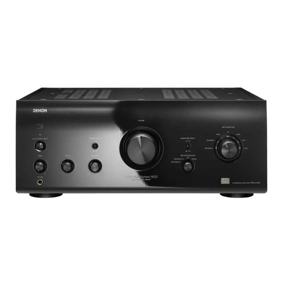
Part Names and Functions
Front Panel

- Power indicator
Indicates the status of the PMA-A100's as follows:For several seconds after the power is turned on Red (blinking) Power "ON" Green Muting Red (blinking) Standby Red Power "OFF" Off - Power switch
(![]() ON/STANDBY
ON/STANDBY ![]() OFF )
OFF )
When set to "![]() ON/STANDBY" the power turns on, and when set to "
ON/STANDBY" the power turns on, and when set to "![]() OFF", the power turns off.
OFF", the power turns off. - Headphone jack (PHONES)
- Plug headphones into this jack.
(The speaker output turns off when the headphones are plugged in.) - To prevent hearing loss, do not raise the volume level excessively when using headphones.
- Plug headphones into this jack.
- BASS control knob
- TREBLE control knob
- BALANCE control knob
- VOLUME control knob
- REC OUT SELECTOR knob
- INPUT SELECTOR knob
Use this knob to select the desired source. - Input indicator
An orange light indicates the selected input. - POWER AMP DIRECT switch
Switching this "![]() ON", allows the device connected to the Power Amp Direct connector on the rear panel to be played. When ON, the input indicator turns off.
ON", allows the device connected to the Power Amp Direct connector on the rear panel to be played. When ON, the input indicator turns off.
Switching it "![]() OFF", allows the program source selected using the INPUT SELECTOR knob to be played. When OFF, the input indicator lights up.
OFF", allows the program source selected using the INPUT SELECTOR knob to be played. When OFF, the input indicator lights up. - SOURCE DIRECT switch
When switched "![]() ON", the signal does not pass through the tone adjustment circuitry (bass, treble and balance), resulting in playback of a higher sound quality.
ON", the signal does not pass through the tone adjustment circuitry (bass, treble and balance), resulting in playback of a higher sound quality.
When set to "![]() OFF", the sound can be adjusted to suit your taste.
OFF", the sound can be adjusted to suit your taste. - Remote control sensor
NOTE
- Functions
![]() ,
, ![]() and
and ![]() are only available when the SOURCE DIRECT switch is "
are only available when the SOURCE DIRECT switch is "![]() OFF".
OFF". - When the VOLUME control knob is turned just past the "12 o'clock" position (over halfway), the effect of BASS and TREBLE adjustments decreases.
- When the VOLUME control knob is turned to maximum or all the way clockwise, the bases and treble can no longer be adjusted.
- When the POWER AMP DIRECT switch is "
![]() ON", adjustment of the volume, balance and tone on the main unit has no effect. Adjust the volume on the input device.
ON", adjustment of the volume, balance and tone on the main unit has no effect. Adjust the volume on the input device. - When the POWER AMP DIRECT switch is "
![]() ON", the main unit outputs at maximum volume. Check the output level on the input device before playing it and adjust the volume accordingly.
ON", the main unit outputs at maximum volume. Check the output level on the input device before playing it and adjust the volume accordingly.
Rear Panel

- Input terminals (INPUTS)
Connect your source equipment here. - Power amplifier direct terminals
(POWER AMP DIRECT)
When a component is connected to these terminals, it feeds directly to the power amp at the source's volume level. - Recording output terminals
(RECORDER-1 and RECORDER-2)
Connect your recording equipment here. - Speaker system terminals
(SPEAKER SYSTEMS)
Connect your speakers here. - AC inlet (AC IN)
Connect the supplied power cord here.
Do not use any cord other than the provided power cord. - PRE OUT connectors
Use this to add equipment such as a power amplifier or subwoofer. - SIGNAL GND (ground) terminal
Connect the ground wire from your turntable here.
NOTE
This terminal is not a safety ground. - CARTRIDGE selection switch
Set this switch to the type of record player cartridge to be used MM (![]() ) or MC (
) or MC (![]() ).
).
NOTE
NEVER insert the short-circuiting pin plug into the recording output or PRE OUT connectors. Doing so could result in damage.

- The PHONO input terminals are equipped with a short pin-plug. Remove this plug to connect a record player.
After removing the short pin-plug, keep it in a safe place so you don't lose it. - Signals are output from the PRE OUT connectors even when using headphones.
Remote Control

CD player operating buttons
The supplied remote control can be used to operate compatible CD players (such as the DCD-A100).
See the CD player's manual for operating instructions.
Amplifier operating buttons
MUTING button
Press this to mute the sound.
The power indicator on the main unit blinks red.
Press again for sound.
VOLUME buttons (![]() )
)
INPUT SELECT buttons
(RECORDER-2, RECORDER-1, PHONO, CD, TUNER, LINE-1, LINE-2)
- The supplied remote control can be used to operate DENON CD players.
- When using it, also refer to the operating instructions of the other devices.
- The remote control may not operate some products.
Connections
Connections for all compatible audio signal format is described in this operating instructions. Please select the type of connections corresponding to the equipment you are connecting.
NOTE
- Do not plug in the power cord until all connections have been completed.
- When making connections, also refer to the operating instructions of the other components.
- Be sure to connect the left and right channels properly (left with left, right with right).
- Do not bundle power cords with connection cables. Doing so can result in humming or noise.
- Do not turn up the volume without a turntable connected to the PHONO input terminals. Doing so will cause humming or noise.
Preparations
Connecting Cables
Select the cables according to the equipment being connected.
Audio cables

Connecting the Audio Equipment
Cautions on playing SA sources:
When regular speakers not compatible with SA sources(DVD Audio discs, Super Audio CDs and other sources, including treble components above the audible range), set the properties of the player(DVD Audio player, Super Audio CD player, etc.) for use with regular speakers (or amplifiers).
The speakers may be damaged if the volume is set too high when playing SA sources. For instructions on player settings, refer to the operating instructions included with the player.
Connecting the Speakers
Connecting the Speaker Cables
Carefully check the left (L) and right (R) channels and + (red) and - (black) polarities on the speakers being connected to the PMA-A100, and be sure to connect the channels and polarities correctly.
- Peel off about 10 mm of sheathing from the tip of the speaker cable, then either twist the core wire tightly or apply solder to it.
![]()
- Turn the speaker terminal counterclockwise to loosen it.
![]()
- Insert the speaker cable's core wire to all the way into the speaker terminal.
![]()
- Turn the speaker terminal clockwise to tighten it.
![]()


Speaker terminal dimensions

NOTE
- Connect the speaker cables so they do not stick out of the speaker terminals. The protection circuit may be activated if the wires touch the rear panel or if the + and - sides touch each other (→ "Protection circuit").
- Never touch the speaker terminals while the power supply is connected. Doing so could result in electric shock.
Speaker impedance
Use speakers with impedances within the ranges shown below to suit how they are used.
| Speakers used | Impedance |
| A or B | 4 ~ 16 Ω/ohms |
| A and B | 8 ~ 16 Ω/ohms |
Protection circuit
The protection circuit is activated in the following situations:
- If the speaker cable wire touches the rear panel or screws or if the speaker cable's + and - sides are touching
- If the surrounding temperature is extremely high
- If the inside of the amplifier gets hot to extended use at a high output
If this happens, unplug the power cord, then check the connections of the speaker cables and input cables. If the becomes very hot. wait for it to cool off and improve the ventilation around it. After doing this, plug the power cord back in.
If the protection circuit is activated even though there are no problems with the ventilation around the set or in its connections. the set may be damaged. Turn off the power and then contact a DENON service center.
Speaker Connections

Bi-wiring Connection
When bi-wiring with bi-wireable speakers, connect the mid and high range terminals to SYSTEM (A) (or SYSTEM (B)), the low range terminals to SYSTEM (B) (or SYSTEM (A)). This enables playback with minimal interference between the high-range speaker unit and the low-range speaker unit.

Connecting Players
If humming or other noise is generated when the ground wire is connected, disconnect it.

Connecting Recorders

Connecting the Power Cord
Wait until all connections have been completed before connecting the power cord.

NOTE
Insert the plugs securely. Loose connections will result in the generation of noise.
Operation
Symbols used to indicate buttons in this manual
Button located on both the main unit and the remote control → BUTTON
Button only on the main unit → <BUTTON>

Preparations Prior to Playing
- Turn VOLUME all the way down.
- Set <SOURCE DIRECT> to "OFF".
- Set <BASS>, <TREBLE> and <BALANCE> to the center positions.
- Turn POWER on.
The power indicator blinks red for several seconds and then lights green.
Starting Playback
- Use INPUT SELECTOR to select the source.
The input indicator for the selected source lights.
[Selectable sources]
![]()
- Play the selected source.
- A djust VOLUME to the desired level.
- A djust the tone with <BASS>, <TREBLE> and <BALANCE>.
- If there is no need to adjust the tone, press <SOURCE DIRECT>.

Starting Recording
- Set <REC OUT SELECTOR> to "SOURCE".
- Use INPUT SELECTOR to select the source to be recorded.
[Selectable sources]
![]()
- Set the recorder to the record mode.
- Start playing the source to be recorded.
NOTE
The recording source switches if INPUT SELECTOR is operated during recording.
Copying Recorders
- Turn <REC OUT SELECTOR> and "RECORDER-1 ► 2" (or "RECORDER-2 ► 1").
[Selectable sources]
![]()
- When copying from a device connected to the "RECORDER-1" terminal to a device connected to the "RECORDER-2" terminal, select "RECORDER-1► 2"
When copying from a device connected to the "RECORDER-2" terminal to a device connected to the "RECORDER-1" terminal, select "RECORDER-2 ► 1".
- When copying from a device connected to the "RECORDER-1" terminal to a device connected to the "RECORDER-2" terminal, select "RECORDER-1► 2"
- Set the device connected to the RECORDER-1 (or RECORDER-2) terminal to the record mode.
- Start playback on the device connected to the RECORDER-2 (or RECORDER-1) terminal.

- The sound to be recorded can be heard by selecting the playback source with INPUT SELECTOR, while the recorded sound can be heard by selecting the recorder.
- When performing these operations, also refer to the operating instructions of the other devices.
NOTE
The sound may be interrupted or noise may be recorded if INPUT SELECTOR is operated during recording.
Troubleshooting
If a problem occurs first check the following:
- Are the connections correct?
- Is the set being operated as described in the owner's manual?
- Are the other components operating properly?
If this unit does not operate properly, check the items listed in the table below. If the problem persist there may be a malfunction. In this case, disconnect the power immediately and contact your retail outlet.
| Symptom | Cause | Countermeasure |
| When the power is turned on, the power indicator does not light and no sound is produced. |
|
|
| The power indicator flashes, and no sound is produced. |
|
|
| The power indicator lights but no sound is produced. |
|
|
| Sound is only produced from the left or right speaker (s). |
|
|
| The left and right of stereo sound is reversed. |
|
|
| Humming sound is heard in the music when playing records. |
|
|
| Howling is produced along with the music if the volume is too high when playing records. |
|
|
| When playing a record, the sound is distorted. |
|
|
Specifications
| Power amplifier section | |
| Rated Output Power: | 2-channel driving (CD → SP OUT) 80 W + 80 W (8 Ω/ohms, 20 Hz ~ 20 kHz, T.H.D. 0.07%) |
| Dynamic power: | 160 W + 160 W (4 Ω/ohms, DIN, 1 kHz, T.H.D. 0.7%) |
| High frequency distortion: | 0.01% (Rated output: –3 dB), 8 Ω/ohms, 1 kHz |
| Output terminals: | Speaker A or B: 4 ~ 16 Ω/ohms A + B: 8 ~ 16 Ω/ohms Suited for headphones/stereo headphones |
| Input Sensitivity/Input Impedance: | P. DIRECT: 0.9 V / 47 kΩ/kohms Amplification factor: 29 dB |
| Pre amplifier section | |
| Equalizer amplifier output: | 150 mV |
| (REC OUT terminals) Input Sensitivity/Input Impedance: | PHONO (MM): 2.5 mV/47 kΩ/kohms PHONO (MC): 200 μV/100 Ω/ohms CD, TUNER, LINE-1, LINE-2, RECORDER-1, RECORDER-2: 135 mV/47 kΩ/kohms (SOURCE DIRECT OFF) 135 mV/23 kΩ/kohms (SOURCE DIRECT ON) |
| RIAA Deviation: | PHONO: 20 Hz ~ 20 kHz ±0.5 dB |
| Maximum Input: | PHONO (MM): 130 mV/1 kHz PHONO (MC): 10 mV/1 kHz |
| Rated Output: | PRE OUT: 0.9 V (Input CD 135 mV) |
| Overall performance SN Ratio (A network): | PHONO (MM): 89 dB (With input terminals short-circuited, 5 mV input signal) PHONO (MC): 74 dB (With input terminals short-circuited, 0.5 mV input signal) CD, TUNER, LINE-1, LINE-2, RECORDER-1, RECORDER-2: 108 dB (input terminals short-circuited) |
| Tone control (bass): | BASS: 100 Hz ±8 dB TREBLE: 10 kHz ±8 dB |
| General | |
| Power supply: | AC 120 V, 60 Hz |
| Power consumption: | 310 W 0.2 W (Standby) |
| Maximum external dimensions: | 17 3/32 (W) x 7 1/8 (H) x 17 29/32 (D) inch (434 (W) x 181 (H) x 455 (D) mm) |
| Weight: | 56 lbs 14.07oz (25.8 kg) |
| Remote control (RC-1138) | |
| Batteries: | R03/AAA Type (two batteries) |
| Maximum external dimensions: | 1 47/64 (W) x 9 9/64 (H) x 55/64 (D) inch (44 (W) x 233 (H) x 22 (D) mm) |
| Weight: | 5.01oz (142 g) (including batteries) |
SAFETY PRECAUTIONS

RISK OF ELECTRIC SHOCK
DO NOT OPEN

TO REDUCE THE RISK OF ELECTRIC SHOCK, DO NOT REMOVE COVER (OR BACK). NO USER-SERVICEABLE PARTS INSIDE. REFER SERVICING TO QUALIFIED SERVICE PERSONNEL.
 The lightning flash with arrowhead symbol, within an equilateral triangle, is intended to alert the user to the presence of uninsulated "dangerous voltage" within the product's enclosure that may be of sufficient magnitude to constitute a risk of electric shock to persons.
 The exclamation point within an equilateral triangle is intended to alert the user to the presence of important operating and maintenance (servicing) instructions in the literature accompanying the appliance.
TO REDUCE THE RISK OF FIRE OR ELECTRIC SHOCK, DO NOT EXPOSE THIS APPLIANCE TO RAIN OR MOISTURE.
 HOT SURFACE. DO NOT TOUCH.
The top surface over the internal heat sink may become hot when operating this product continuously.
Do not touch hot areas, especially around the "Hot surface surface mark" and the top panel.
IMPORTANT SAFETY INSTRUCTIONS
- Read these instructions.
- Keep these instructions.
- Heed all warnings.
- Follow all instructions.
- Do not use this apparatus near water.
- Clean only with dry cloth.
- Do not block any ventilation openings. Install in accordance with the manufacturer's instructions.
- Do not install near any heat sources such as radiators, heat registers, stoves, or other apparatus (including amplifiers) that produce heat.
- Do not defeat the safety purpose of the polarized or grounding-type plug. A polarized plug has two blades with one wider than the other. A grounding type plug has two blades and a third grounding prong. The wide blade or the third prong are provided for your safety. If the provided plug does not fit into your outlet, consult an electrician for replacement of the obsolete outlet.
- Protect the power cord from being walked on or pinched particularly at plugs, convenience receptacles, and the point where they exit from the apparatus.
- Only use attachments/accessories specified by the manufacturer.
- Use only with the cart, stand, tripod, bracket, or table specified by the manufacturer, or sold with the apparatus. When a cart is used, use caution when moving the cart/ apparatus combination to avoid injury from tip-over.
![]()
- Unplug this apparatus during lightning storms or when unused for long periods of time.
- Refer all servicing to qualified service personnel. Servicing is required when the apparatus has been damaged in any way, such as power-supply cord or plug is damaged, liquid has been spilled or objects have fallen into the apparatus, the apparatus has been exposed to rain or moisture, does not operate normally, or has been dropped.
- Batteries shall not be exposed to excessive heat such as sunshine, fire or the like.

To completely disconnect this product from the mains, disconnect the plug from the wall socket outlet.
The mains plug is used to completely interrupt the power supply to the unit and must be within easy access by the user.
NOTE ON USE

- Avoid high temperatures. Allow for sufficient heat dispersion when installed in a rack.
- Handle the power cord carefully. Hold the plug when unplugging the cord.
- Keep the unit free from moisture, water, and dust.
- Unplug the power cord when not using the unit for long periods of time.
- Do not obstruct the ventilation holes.
- Do not let foreign objects into the unit.
- Do not let insecticides, benzene, and thinner come in contact with the unit.
- Never disassemble or modify the unit in any way.
- Ventilation should not be impeded by covering the ventilation openings with items, such as newspapers, tablecloths or curtains.
- Naked flame sources such as lighted candles should not be placed on the unit.
- Observe and follow local regulations regarding battery disposal.
- Do not expose the unit to dripping or splashing fluids.
- Do not place objects filled with liquids, such as vases, on the unit.
- Do not handle the mains cord with wet hands.
- When the switch is in the OFF position, the equipment is not completely switched off from MAINS.
- The equipment shall be installed near the power supply so that the power supply is easily accessible.
CAUTIONS ON INSTALLATION

- For proper heat dispersal, do not install this unit in a confined space, such as a bookcase or similar enclosure.
- More than 0.3 m is recommended.
- Do not place any other equipment on this unit.
www.denon.com

Documents / ResourcesDownload manual
Here you can download full pdf version of manual, it may contain additional safety instructions, warranty information, FCC rules, etc.
Advertisement


Need help?
Do you have a question about the PMA-A100 and is the answer not in the manual?
Questions and answers