Denon POA-A1HD - Reference Power Amplifier 150 Watts x 10 Channel Manual
- Command list (9 pages) ,
- Owner's manual (19 pages) ,
- Service manual (64 pages)
Advertisement
Getting Started
Thank you for purchasing this DENON product. To ensure proper operation, please read this owner's manual carefully before using the product. After reading them, be sure to keep them for future reference.
THX Ultra2
Before any home theater component can be THX Ultra2 certified, it must incorporate all the features above and also pass a rigorous series of quality and performance tests. Only then can a product feature the THX Ultra2 logo, which is your guarantee that the Home Theater products you purchase will give you superb performance for many years to come. THX Ultra2 requirements cover every aspect of the product including power amplifier performance, pre-amplifier performance and operation, as well as hundreds of other parameters in both the digital and analog domain.
In addition to improvements to the power amplifier with respect to previous THX Ultra standards, three surround modes have been added: the THX Ultra2 Cinema mode, THX Music Mode and THX Games Mode.
- "THX" and "Ultra2" are trademarks of THX Ltd. THX may be registered in some jurisdictions. All rights reserved.
- In the NORMAL connection and Bi-AMP connection operation mode, POA-A1HD has acquired THX certification. To play back data in a manner that complies with the THX standard, use the NORMAL connection or Bi-AMP connection mode.
Accessories
Check that the following parts are supplied with the product.
 | Owner's manual | 1 |
 | Service station list | 1 |
 | Power cord (Cord length: Approx. 1.5 m) | 1 |
 | Control link cable (Cord length: Approx. 3 m) | 1 |
Cautions on Handling
- Before turning the power switch on
Check once again that all connections are correct and that there are no problems with the connection cables. - Power is supplied to some of the circuitry even when the unit is set to the standby mode. When traveling or leaving home for long periods of time, be sure to unplug the power cord from the power outlet.
- About condensation
If there is a major difference in temperature between the inside of the unit and the surroundings, condensation (dew) may form on the operating parts inside the unit, causing the unit not to operate properly. If this happens, let the unit sit for an hour or two with the power turned off and wait until there is little difference in temperature before using the unit. - Cautions on using mobile phones
Using a mobile phone near this unit may result in noise. If so, move the mobile phone away from this unit when it is in use. - Moving the unit
Turn off the power and unplug the power cord from the power outlet.
Next, disconnect the connection cables to other system units before moving the unit. - Note that the illustrations in these instructions may differ from the actual unit for explanation purposes.
Cautions on Installation
Note:
For proper heat dispersal, do not install this unit in a confi ned space, such as a bookcase or similar enclosure.

NOTE
- Since this unit is very heavy, when installing it on a rack etc, the maximum load capacity of the rack should always be checked first. Please refer to the user manual for the rack for the maximum load capacity.
- Always have at least two people work together to move the POA- A1HD.
Preparations
Before using this unit, the following steps should be followed, according to the situation in which the unit will be used.

Set the number of units
"OPTION/1/2 mode selection"
Control link connection
"Connect to AVP-A1HD"
Set operation mode and input mode from AVP-A1HD and connect the speakers
All setup options are carried out using the AVP-A1HD setup menu. ("Connect to AVP-A1HD")
Input from source other than AVP-A1HD
"Connection and Settings"
Set the operation mode and input mode, then connect the speakers
- Normal Connections
- Bi-Amp Connections
- Bridge Connections
Set the control method
"Connecting the External Controller"
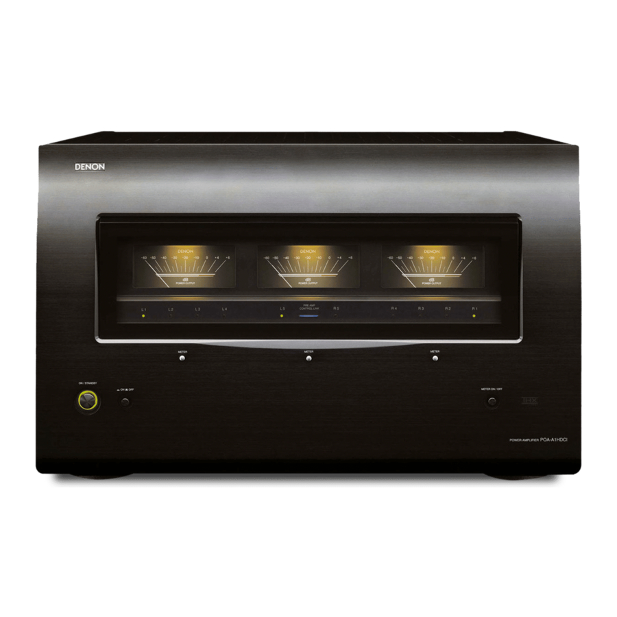
Part Names and Functions
Front Panel

- Power operation button (ON/STANDBY)
- Power switch (
![]() ON
ON ![]() OFF)
OFF) - Left channel meter select button (METER)
- Left channel meter indicators (L1 / L2 / L3 / L4)
- Left channel level meter
- Center channel meter indicators (L5 / R5)
- PRE AMP CONTROL LINK indicator
- Center channel meter select button (METER)
- Center channel level meter
- Right channel meter select button (METER)
- Right channel meter indicators (R1 / R2 / R3 / R4)
- Right channel level meter
- METER ON/OFF button
 ON
ON  OFF)
OFF) About channel level meter
You can select the output level (dB indicator) of each power amp channel to check the meter.
If a sine wave is input, the output power for the meter indicator is as shown in the following table.
- When NORMAL connection or Bi-AMP connection is used
| Output indicator | 4 Ω/ohms load | 6 Ω/ohms load | 8 Ω/ohms load |
| 0 (dB) | 300 (W) | 200 (W) | 150 (W) |
| –10 (dB) | 30 (W) | 20 (W) | 15 (W) |
| –20 (dB) | 3 (W) | 2 (W) | 1.5 (W) |
| –30 (dB) | 300 (mW) | 200 (mW) | 150 (mW) |
| –40 (dB) | 30 (mW) | 20 (mW) | 15 (mW) |
| –50 (dB) | 3 (mW) | 2 (mW) | 1.5 (mW) |
- When BRIDGE connection is used
| Output indicator | 4 Ω/ohms load | 6 Ω/ohms load | 8 Ω/ohms load |
| 0 (dB) | 1200 (W) b | 800 (W) b | 600 (W) b |
| –10 (dB) | 120 (W) | 80 (W) | 60 (W) |
| –20 (dB) | 12 (W) | 8 (W) | 6 (W) |
| –30 (dB) | 1200 (mW) | 800 (mW) | 600 (mW) |
| –40 (dB) | 120 (mW) | 80 (mW) | 60 (mW) |
| –50 (dB) | 12 (mW) | 8 (mW) | 6 (mW) |
- Possible output by POA-A1HD is up to the rated output.
NOTE
When outputting a program source that has data such as SACD, which is higher than the audible band, the indicator moves differently than the volume you hear.
Rear Panel

- Input select switches
- Operation mode select switch
- Mode select switch (MODE)
- CONTROL LINK connectors
- Control select switch (CONTROL)
- TRIGGER IN jack
- RS-232C connector
- AC inlet (AC IN)
- Speaker terminals (SPEAKERS)
- XLR input connectors
- RCA input connectors
NOTE
The  ~
~  and
and  must be set before turning the power on. Settings which are changed after powering on will not be registered. In such cases, the power should be switched off and on again.
Connections and Settings
Connections for all compatible audio signal formats are described in these operating instructions.
Please select the types of connections suited for the equipment you are connecting.
With some types of connections, certain settings must be made on the POA-A1HD. For details, refer to the instructions for the respective connection items below.
NOTE
- Do not plug in the power cord until all connections have been completed.
- When making connections, also refer to the operating instructions of the other components.
- Be sure to connect the left and right channels properly (left with left, right with right).
- Do not bundle power cords together with connection cables. Doing so can result in humming or noise.
Preparations
Cables Used for Connections
Select the cables according to the equipment being connected.
| Audio cables | Signal direction |
 Analog connections (XLR) Balanced cable |  Audio signal |
 Analog connections (RCA) Pin-plug cable | |
 Speaker connections Speaker cables |
Connecting the speaker cables
Carefully check the left (L) and right (R) channels and + (red) and – (black) polarities on the speakers being connected to the POA-A1HD, and be sure to interconnect the channels and polarities correctly.
- Peel off about 10 mm of sheathing from the tip of the speaker cable, then either twist the core wire tightly or terminate it.
![]()
- Turn the speaker terminal counterclockwise to loosen it.
![]()
- Insert the speaker cable's core wire to the hilt into the speaker terminal.
![]()
- Turn the speaker terminal clockwise to tighten it.
![]()


NOTE
- Connect the speaker cables in such a way that they do not stick out of the speaker terminals. The protection circuit may be activated if the core wires touch the rear panel or if the + and – sides touch each other (see Protection circuit).
![shock hazard]() Never touch the speaker terminals while the power supply is connected. Doing so could result in electric shock.
Never touch the speaker terminals while the power supply is connected. Doing so could result in electric shock.
Protection circuit
If speakers with an impedance lower than specified are used for an extended period of time with the volume turned up high, the temperature may rise, activating the protection circuit.
When the protection circuit is activated, the speaker output is shut off and the power indicator flashes red. If this happens, unplug the power cord, then check the speaker cable and input cable connections. If the set is extremely hot, wait for it to cool off and improve ventilation around it. Once this is done, plug the power cord back in and turn the set's power back on.
If the protection circuit is activated again even though there are no problems in the ventilation around the set nor in the connections, the set may be damaged. Turn the power off, then contact a DENON service center.
Settings
NOTE
The MODE, CONTROL, Operation mode select switch and Input select switch must be set before turning the power on. Settings which are changed after powering on will not be registered. In such cases, the power should be switched off and on again.

[Rear panel]
Change the input mode
Change the input mode for each channel (L1 ~ L5, R1 ~ R5).
Set the Input select switch.
- XLR: Use XLR terminal.
- RCA: Use RCA terminal.
- OFF: Channel is not used.
NOTE
- When the input and Input select switch setting on the unit are different, the unit does not operate.
- If CONTROL is set to "AVP", this setting is invalid.
Change the operation mode
Change the operation mode for each channel (L1 ~ L5, R1 ~ R5) or pair channel (L1 / L2, L3 / L4, L5 / R5, R1 / R2, R3 / R4).
Bi-AMP / NORMAL / BRIDGE mode selection
Set how to use the power amp with each channel.
Set the Operation mode select switch.
- Bi-AMP: Used for Bi-Amp connection.
- NORMAL: Used for NORMAL connection.
- BRIDGE: Used for BRIDGE connection.
NOTE
- Channels that have the input mode set to "OFF" can not be selected.
- If CONTROL is set to "AVP", this setting is invalid.
Change the control mode
Select the option suited for the equipment operating the unit.
Select CONTROL.
- AVP: Operates the unit from the AVP-A1HD
- OFF: Control mode is not used.
- EXTERNAL: Operates the unit from equipment connected to the RS-232C connector or TRIGGER IN jack.

When CONTROL is set to " AVP", the PRE AMP CONTROL LINK indicator lights in blue.
OPTION / 1 / 2 mode selection
Use control link to connect POA-A1HD and AVP-A1HD and switch POA-A1HD according to the number of units to be connected.
Select MODE.
- OPTION: For future use, if the range of functions is expanded.
- 1: Used as the first unit when one POA-A1HD unit is used or two POA-A1HD units are connected.
- 2: Used as the second unit when two POA-A1HD units are connected.
Connect to AVP-A1HD
This example shows the connection of an AV sound preamplifier AVP-A1HD (sold separately) to the unit.
To operate POA-A1HD from AVP-A1HD, connect the control link cable, set CONTROL switch to "AVP" and then set MODE switch to "1".
- Please refer to the AVP-A1HD owner's manual for setup and operation instructions.
- When connecting, please also refer to the AVP-A1HD owner's manual.
NOTE
Always set the Input select switch for channels not in use to "OFF".
Connecting to an RCA input terminal

Example: 7-channels (NORMAL setting)
Connecting to an XLR input terminal

Example: 7-channels (NORMAL setting)
Connecting 2 POA-A1HD units to the AVP-A1HD
The AVP-A1HD can be operated when connected to 2 POA-A1HD units.
Settings
- Connect the equipment using a control link cable.
- Set CONTROL switch of two POA-A1HD units to "AVP".
- Set MODE switch of POA-A1HD, which is connected to AVP-A1HD, to "1", and the other MODE switch of POA-A1HD to "2".
Please refer to the AVP-A1HD owner's manual for setup and operation instructions.

Settings and Connections
Set the rear panel "Operation mode select switch" and "Input select switch" according to the connection method.
NOTE
The Operation mode select switch and Input select switch must be set before turning the power on. Settings which are changed after powering on will not be registered. In such cases, the power should be switched off and on again.
Normal Connections
Connection for signal input to each channel to be output from the channel's speaker terminal.
- Set each switch as shown below.
- Set the Operation mode select switch to "NORMAL".
- Set the Input select switch according to the input.
- For RCA input - Set to "RCA".
- For XLR input - Set to "XLR".

Example: Normal connection to the  channel
- Setup each channel (
![]() ~
~ ![]() ,
, ![]() ~
~ ![]() ) using the same steps.
) using the same steps.
 ~
~  ,
,  ~
~  ) using the same steps.
NOTE
- The same signal is output to speakers A and B.
- Please use the following speaker impedance.
| When using only speaker A or B | 4 ~ 16 Ω/ohms |
| When using speakers A and B at the same time | 8 ~ 16 Ω/ohms |
Bi-wiring connection
When using speakers that have input terminals for both woofer units and tweeter units, this connection allows for the same signal to be output from each unit. With this connection the interference between signals for the woofer unit and tweeter unit is low so that you can enjoy high quality sound in playback.

NOTE
When using Bi-Wiring connection use 4 ~ 16 Ω/ohms speakers for the impedance.
Bi-Amp Connections
When using speakers that have input terminals for both woofer units and tweeter units, this connection outputs one input signal from the two amps on the main unit to each of these units. With this connection the interference between signals for the woofer unit and tweeter unit is eliminated so that you can enjoy high quality sound in playback.
- Bi-Amp output is setup using the following combination of channels. The input terminals to be used are as follows.
![]() and
and ![]() input terminal:
input terminal: ![]() channels
channels![]() and
and ![]() input terminal:
input terminal: ![]() channels
channels![]() and
and ![]() input terminal:
input terminal: ![]() channels
channels![]() and
and ![]() input terminal:
input terminal: ![]() channels
channels![]() and
and ![]() input terminal:
input terminal: ![]() channels
channels
- Set each switch as shown below.
- Set the Operation mode select switch to "Bi-AMP".
- Set the Input select switch according to the input.
- For RCA input - Set to "RCA".
- For XLR input - Set to "XLR".
 and
and  input terminal:
  and
and  input terminal:
  and
and  input terminal:
  and
and  input terminal:
 NOTE
The input terminal (channel  in case of and
  ) that is not used for this setting becomes invalid regardless of the status of Input select switch.
Example: Bi-Amp connection using and channels
- Setup each pair channel using the same steps.


NOTE
- The same signal is output to channel
![]() and channel
and channel ![]()
- No signal is output from the speaker B terminal.
- Use speakers with an impedance of 4 ~ 16 Ω /ohms.
SAFETY PRECAUTIONS

RISK OF ELECTRIC SHOCK
DO NOT OPEN
TO REDUCE THE RISK OF ELECTRIC SHOCK, DO NOT REMOVE COVER (OR BACK). NO USER-SERVICEABLE PARTS INSIDE. REFER SERVICING TO QUALIFIED SERVICE PERSONNEL.
 | The lightning flash with arrowhead symbol, within an equilateral triangle, is intended to alert the user to the presence of uninsulated "dangerous voltage" within the product's enclosure that may be of sufficient magnitude to constitute a risk of electric shock to persons. |
 | The exclamation point within an equilateral triangle is intended to alert the user to the presence of important operating and maintenance (servicing) instructions in the literature accompanying the appliance. |


TO REDUCE THE RISK OF FIRE OR ELECTRIC SHOCK, DO NOT EXPOSE THIS APPLIANCE TO RAIN OR MOISTURE.

To completely disconnect this product from the mains, disconnect the plug from the wall socket outlet.
The mains plug is used to completely interrupt the power supply to the unit and must be within easy access by the user.
NOTE ON USE
- Avoid high temperatures. Allow for sufficient heat dispersion when installed in a rack.
![]()
- Handle the power cord carefully. Hold the plug when unplugging the cord.
![]()
- Keep the unit free from moisture, water, and dust.
![]()
- Unplug the power cord when not using the unit for long periods of time.
![]()
- Do not obstruct the ventilation holes.
* (For apparatuses with ventilation holes)
![]()
- Do not let foreign objects into the unit.
![]()
- Do not let insecticides, benzene, and thinner come in contact with the unit.
![]()
- Never disassemble or modify the unit in any way.
![]()


- The ventilation should not be impeded by covering the ventilation openings with items, such as newspapers, tablecloths, curtains, etc.
- No naked flame sources, such as lighted candles, should be placed on the unit.
- Observe and follow local regulations regarding battery disposal.
- Do not expose the unit to dripping or splashing fluids.
- Do not place objects filled with liquids, such as vases, on the unit.

Documents / ResourcesDownload manual
Here you can download full pdf version of manual, it may contain additional safety instructions, warranty information, FCC rules, etc.
Download Denon POA-A1HD - Reference Power Amplifier 150 Watts x 10 Channel Manual
Advertisement


Need help?
Do you have a question about the POA-A1HD and is the answer not in the manual?
Questions and answers