Denon POA-A1HDCI - POWER AMPLIFIER Manual
- Service manual (64 pages) ,
- Owner's manual (23 pages) ,
- Command list (9 pages)
Advertisement
- 1 Getting Started
- 2 Connections and Settings
- 3 Operations
- 4 Troubleshooting
- 5 Specifications
- 6 IMPORTANT SAFETY INSTRUCTIONS
- 7 Documents / Resources
Getting Started
To ensure proper operation, please read this owner's manual carefully before using the product.
After reading them, be sure to keep them for future reference.
Accessories
Check that the following parts are supplied with the product.
- Owner's manual - 1
- Warranty (for North America model only) - 1
- Service station list - 1
- Power cord (Cord length: Approx. 5 ft / 1.5 m) - 1
![]()
- Control link cable (Cord length: Approx. 10 ft / 3 m) - 1

Cautions on Handling
- Before turning the power switch on
Check once again that all connections are correct and that there are no problems with the connection cables. - Power is supplied to some of the circuitry even when the unit is set to the standby mode. When traveling or leaving home for long periods of time, be sure to unplug the power cord from the power outlet.
- About condensation
If there is a major difference in temperature between the inside of the unit and the surroundings, condensation (dew) may form on the operating parts inside the unit, causing the unit not to operate properly.
If this happens, let the unit sit for an hour or two with the power turned off and wait until there is little difference in temperature before using the unit. - Cautions on using mobile phones
Using a mobile phone near this unit may result in noise. If so, move the mobile phone away from this unit when it is in use. - Moving the unit
Turn off the power and unplug the power cord from the power outlet.
Next, disconnect the connection cables to other system units before moving the unit. - Note that the illustrations in these instructions may differ from the actual unit for explanation purposes.
Cautions on Installation
Note: For proper heat dispersal, do not install this unit in a confined space, such as a bookcase or similar enclosure.

NOTE
- Since this unit is very heavy, when installing it on a rack etc, the maximum load capacity of the rack should always be checked first. Please refer to the user manual for the rack for the maximum load capacity.
- Always have at least two people work together to move the POA-A1HDCI.
Preparations
Before using this unit, the following steps should be followed, according to the situation in which the unit will be used.

Part Names and Functions
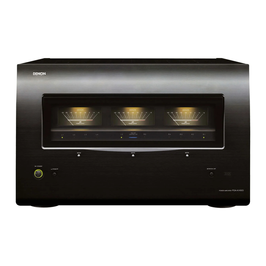
Front Panel

- Power operation button (ON/STANDBY)
- Power indicator
- Power switch (
![]() ON
ON ![]() OFF)
OFF) - Left channel meter select button (METER)
- Left channel meter indicators (L1 / L2 / L3 / L4)
- Left channel level meter
- Center channel meter indicators (L5 / R5)
- PRE AMP CONTROL LINK indicator
- Center channel meter select button (METER)
- Center channel level meter
- Right channel meter select buttons (METER)
- Right channel meter indicators (R1 / R2 / R3 / R4)
- Right channel level meter
- METER ON/OFF button
About channel level meter
You can select the output level (dB indicator) of each power amp channel to check the meter.
If a sine wave is input, the output power for the meter indicator is as shown in the following table.
- When NORMAL connection or Bi-AMP connection is used
Output indicator 4 Ω/ohms load 6 Ω/ohms load 8 Ω/ohms load 0 (dB) 300 (W) 200 (W) 150 (W) –10 (dB) 30 (W) 20 (W) 15 (W) –20 (dB) 3 (W) 2 (W) 1.5 (W) –30 (dB) 300 (mW) 200 (mW) 150 (mW) –40 (dB) 30 (mW) 20 (mW) 15 (mW) –50 (dB) 3 (mW) 2 (mW) 1.5 (mW) - When BRIDGE connection is used
Output indicator 4 Ω/ohms load 6 Ω/ohms load 8 Ω/ohms load 0 (dB) 1200 (W) * 800 (W) * 600 (W) * –10 (dB) 120 (W) 80 (W) 60 (W) –20 (dB) 12 (W) 8 (W) 6 (W) –30 (dB) 1200 (mW) 800 (mW) 600 (mW) –40 (dB) 120 (mW) 80 (mW) 60 (mW) –50 (dB) 12 (mW) 8 (mW) 6 (mW)
* Possible output by POA-A1HDCI is up to the rated output.
NOTE
When outputting a program source that has data such as SACD, which is higher than the audible band, the indicator moves differently than the volume you hear.
Rear Panel

- Input select switches
- Operation mode select switch
- Mode select switch (MODE)
- CONTROL LINK connectors
- Control select switch (CONTROL)
- TRIGGER IN jack
- RS-232C connector
- AC inlet (AC IN)
- Speaker terminals (SPEAKERS)
- XLR input connectors
- RCA input connectors
NOTE
The 1 ~ 3 and 5 must be set before turning the power on. Settings which are changed after powering o on will not be registered. In such cases, the power should be switched off and on again.
Connections and Settings
Connections for all compatible audio signal formats are described in these operating instructions. Please select the types of connections suited for the equipment you are connecting.
With some types of connections, certain settings must be made on the POA-A1HDCI. For details, refer to the instructions for the respective connection items below.
NOTE
- Do not plug in the power cord until all connections have been completed.
- When making connections, also refer to the operating instructions of the other components.
- Be sure to connect the left and right channels properly (left with left, right with right).
- Do not bundle power cords together with connection cables. Doing so can result in humming or noise.
Preparations
Cables Used for Connections
Select the cables according to the equipment being connected.
| Audio cables | Signal direction |
| Analog connections (XLR) Analog connections (RCA) Speaker connections | Audio signal: |


Connecting the speaker cables
Carefully check the left (L) and right (R) channels and + (red) and – (black) polarities on the speakers being connected to the POA-A1HDCI, and be sure to interconnect the channels and polarities correctly.
- Peel off about 0.03 ft / 10 mm of sheathing from the tip of the speaker cable, then either twist the core wire tightly or terminate it.
![]()
- Turn the speaker terminal counterclockwise to loosen it.
![]()
- Insert the speaker cable's core wire to the hilt into the speaker terminal.
![]()
- Turn the speaker terminal clockwise to tighten it.
![]()


| When using a banana plug | |
Tighten the speaker terminal firmly before inserting the banana plug. |
NOTE
- Connect the speaker cables in such a way that they do not stick out of the speaker terminals. The protection circuit may be activated if the core wires touch the rear panel or if the + and – sides touch each other (→ Protection circuit).
- Never touch the speaker terminals while the power supply is connected. Doing so could result in electric shock.
| Protection circuit |
| If speakers with an impedance lower than specified are used for an extended period of time with the volume turned up high, the temperature may rise, activating the protection circuit. When the protection circuit is activated, the speaker output is shut off and the power indicator flashes red. If this happens, unplug the power cord, then check the speaker cable and input cable connections. If the set is extremely hot, wait for it to cool off and improve ventilation around it. Once this is done, plug the power cord back in and turn the set's power back on. If the protection circuit is activated again even though there are no problems in the ventilation around the set nor in the connections, the set may be damaged. Turn the power off, then contact a DENON service center. |
Settings
NOTE
The MODE, CONTROL, Operation mode select switch and Input select switch must be set before turning the power on. Settings which are changed after powering on will not be registered. In such cases, the power should be switched off and on again.
[Rear panel]

Change the input mode
Change the input mode for each channel (L1 ~ L5, R1 ~ R5).
Set the Input select switch.
- XLR: Use XLR terminal.
- RCA: Use RCA terminal.
- OFF: Channel is not used.
NOTE
- When the input and Input select switch setting on the unit are different, the unit does not operate.
- If CONTROL is set to "AVP", this setting is invalid.
Change the operation mode
Change the operation mode for each channel (L1 ~ L5, R1 ~ R5) or pair channel (L1 / L2, L3 / L4, L5 / R5, R1 / R2, R3 / R4).
Bi-AMP / NORMAL / BRIDGE mode selection
Set how to use the power amp with each channel.
Set the Operation mode select switch.
- Bi-AMP: Used for Bi-Amp connection.
- NORMAL: Used for NORMAL connection.
- BRIDGE: Used for BRIDGE connection.
NOTE
- Channels that have the input mode set to "OFF" can not be selected.
- If CONTROL is set to "AVP", this setting is invalid.
Change the control mode
Select the option suited for the equipment operating the unit.
Select CONTROL.
- AVP: Operates the unit from the AVP-A1HDCI.
- OFF: Control mode is not used.
- EXTERNAL: Operates the unit from equipment connected to the RS-232C connector or TRIGGER IN jack.
![]()
When CONTROL is set to" AVP", the PRE AMP CONTROL LINK indicator lights in blue.
OPTION / 1 / 2 mode selection
Use control link to connect POA-A1HDCI and AVP-A1HDCI and switch POA-A1HDCI according to the number of units to be connected.
Select MODE.
- OPTION: For future use, if the range of functions is expanded.
- 1: Used as the first unit when one POA-A1HDCI unit is used or two POA-A1HDCI units are connected.
- 2: Used as the second unit when two POA-A1HDCI units are connected.
Connect to AVP-A1HDCI
This example shows the connection of an AV sound preamplifier AVP-A1HDCI (sold separately) to the unit.
To operate POA-A1HDCI from AVP-A1HDCI, connect the control link cable, set CONTROL switch to "AVP" and then set MODE switch to "1".

- Please refer to the AVP-A1HDCI owner's manual for setup and operation instructions.
- When connecting, please also refer to the AVP-A1HDCI owner's manual.
NOTE
Always set the Input select switch for channels not in use to "OFF".
Connecting to an RCA input terminal
Example: 7-channels (NORMAL setting)

Connecting to an XLR input terminal
Example: 7-channels (NORMAL setting)

Connecting 2 POA-A1HDCI units to the AVP-A1HDCI
The AVP-A1HDCI can be operated when connected to 2 POA-A1HDCI units.
Settings
- Connect the equipment using a control link cable.
- Set CONTROL switch of two POA-A1HDCI units to "AVP".
- Set MODE switch of POA-A1HDCI, which is connected to AVP-A1HDCI, to "1", and the other MODE switch of POA-A1HDCI to "2".
![]()
Please refer to the AVP-A1HDCI owner's manual for setup and operation instructions.

Settings and Connections
Set the rear panel "Operation mode select switch" and "Input select switch" according to the connection method.
NOTE
The Operation mode select switch and Input select switch must be set before turning the power on. Settings which are changed after powering on will not be registered. In such cases, the power should be switched off and on again.
Normal Connections
Connection for signal input to each channel to be output from the channel's speaker terminal.
- Set each switch as shown below.
- Set the Operation mode select switch to "NORMAL".
- Set the Input select switch according to the input.
- For RCA input - Set to "RCA".
- For XLR input - Set to "XLR".
Example: Normal connection to the R1 channel

* Setup each channel (L1 ~ L5, R1 ~ R5) using the same steps.
NOTE
- The same signal is output to speakers A and B.
- Please use the following speaker impedance.
- When using only speaker A or B - 4 ~ 16 Ω/ohms
- When using speakers A and B at the same time - 8 ~ 16 Ω/ohms
Bi-wiring connection
When using speakers that have input terminals for both woofer units and tweeter units, this connection allows for the same signal to be output from each unit.
With this connection the interference between signals for the woofer unit and tweeter unit is low so that you can enjoy high quality sound in playback.

NOTE
When using Bi-Wiring connection use 4 ~ 16 Ω/ohms speakers for the impedance.
Bi-Amp Connections
When using speakers that have input terminals for both woofer units and tweeter units, this connection outputs one input signal from the two amps on the main unit to each of these units. With this connection the interference between signals for the woofer unit and tweeter unit is eliminated so that you can enjoy high quality sound in playback.
- Bi-Amp output is setup using the following combination of channels. The input terminals to be used are as follows.
- R1 and R2 input terminal: R2 channels
- R3 and R4 input terminal: R4 channels
- R5 and L5input terminal: L5 channels
- L3 and L4 input terminal: L3 channels
- L1 and L2 input terminal: L1 channels
- Set each switch as shown below.
- Set the Operation mode select switch to "Bi-AMP".
- Set the Input select switch according to the input.
- For RCA input - Set to "RCA".
- For XLR input - Set to "XLR".
NOTE
The input terminal (channel R1 in case of R1 and R2) that is not used for this setting becomes invalid regardless of the status of Input select switch.
Example: Bi-Amp connection using R1 and R2 channels

* Setup each pair channel using the same steps.
NOTE
- The same signal is output to channelR1 and channel R2.
- No signal is output from the speaker B terminal.
- Use speakers with an impedance of 4 ~ 16 Ω/ohms.
Bridge Connections
This connection is used to use two power amps to output opposite phase signals generated from one input signal using two power amp units.
By connecting the output (+ side) of the two power amps to the speaker, a larger output than in a normal connection is possible.
- Bridge output is setup using the following combination of channels. The input terminals to be used are as follows.
- R1 and R2 input terminal: R2 channels
- R3 and R4 input terminal: R4 channels
- R5 and L5input terminal: L5 channels
- L3 and L4 input terminal: L3 channels
- L1 and L2 input terminal: L1 channels
- Set each switch as shown below.
- Set the Operation mode select switch to "BRIDGE".
- Set the Input select switch according to the input.
- For RCA input - Set to "RCA".
- For XLR input - Set to "XLR".
NOTE
- The input terminal (channel R1 in case of R1 and R2) that is not used for this setting becomes invalid regardless of the status of Input select switch.
- About output by this connection, the voltage applied to the speaker is 6 dB higher than the output when the normal connection is used. Adjust the input signal using the volume of the pre-amp when connecting.
Example: Bridge connection using R1 and R2 channels

* Setup each pair channel using the same steps.
NOTE
- No signal is output from the "–" terminal of speaker A, or the speaker B terminal.
- Use speakers with an impedance of 4 ~ 16 Ω/ohms.
- Do not connect a speaker using other than the specified combination of channels.
Connecting the External Controller
When using the following functions, set the CONTROL switch to "EXTERNAL".
RS-232C connector
This connector is used for an external controller.

* If you use an external controller to operate the unit via the RS-232C terminal, you must confirm the following beforehand.
- Turn on the POA-A1HDCI's power.
- Turn off the POA-A1HDCI's power from the external controller.
- POA-A1HDCI enters the standby status.
Trigger input jacks
Connect to external equipment that has a trigger output terminal. When the equipment connected by this terminal is powered on / off, the power of the unit can be changed from on / standby.

Connecting the Power Cord
Wait until all connections have been completed before connecting the power cord.

* In order to fully demonstrate the ability of POA-A1HDCI, connect the unit to a larger current capacity outlet (at least 15 A is recommended). Also, be sure that the total power consumption of all devices connected to the outlet does not exceed the outlet capacity.
NOTE
- Insert the AC plugs securely. Incomplete connections could cause noise.
- The power plug must be connected to a wall-mounted power outlet.
- Do not connect the unit to an integrated AC outlet on another product or to extension cord.
Once Connections are Completed
→ Turning the Power On
Operations
[Front panel]

Turning the Power On
- Press POWER.
The power indicator lights red and the power is set to the standby mode. - Press ON/STANDBY.
The power indicator flashes in green for several seconds and the power is turned on.
NOTE
Before tuning on the power, lower the sound volume of the connected equipment.
Turning the Power Off
- Press ON/STANDBY.
The power is set to the standby mode. - Press POWER.
The power indicator turns off, and so does the power.
NOTE
Power continues to be supplied to some of the circuitry even when the power is in the standby mode. When leaving home for long periods of time or when traveling, either press POWER to turn off the power, or unplug the power cord from the power outlet.
Select the channel to display on the channel level meter
Press METER.
The indicator of the selected channel meter turns green and the output level of the selected channel is indicated on the meter.
- L channel meter select button:
![]()
- Center channel meter select button:
![]()
- R channel meter select button:
![]()


![]()
- Channels for which Input select switch is set to "OFF" are skipped.
- In the case of bi-amp connection, the indicator of the input-side channel meter of the selected channel pair turns green.
- In the case of a bridge connection, the indicator of the channel meter of the selected channel pair turns green.
Set the channel level meter
Set ON/OFF of all channel level meters.
Press METER ON/OFF.
- ON: The channel level meter is illuminated and the channel level meter operates.
- OFF: The channel level meter illumination and the channel meter indicator turn off and the channel level meter does not operate.
![]()
The PRE AMP CONTROL LINK indicator goes off if set to "OFF" with the AVP-A1HDCI connected to the control link.
Troubleshooting
If a problem should arise, first check the following:
- Are the connections correct?
- Is the set being operated as described in the owner's manual?
- Are the other components operating properly?
If this unit does not operate properly, check the items listed in the table below. Should the problem persist, there may be a malfunction.
In this case, disconnect the power immediately and contact your store of purchase.
| Symptom | Cause | Countermeasure |
| Power does not turn on, or turns off directly after it was turned on. |
|
|
| No sound is produced from speakers. |
|
|
| Power turns off suddenly and power indicator flashes red. |
|
|
Specifications
Power amplifier section
| |
| Normal connections: | L1 / R1: L2 / R2: L3 / R3: L4 / R4: L5 / R5: |
| Bridge connections: | L1 + L2: L3 + L4: L5 + R5: R1 + R2: R3 + R4: |
| 10 Hz ~ 100 kHz (8 Ω/ohms, +1, –3 dB (at 1 W) ) |
| A or B 4 ~ 16 Ω/ohms A + B 8 ~ 16 Ω/ohms Bi-wiring 4 ~ 16 Ω/ohms |
General
| Power supply: | AC 120 V, 60 Hz |
| Power consumption: | 12 A 0.3 W (Standby) |
| Maximum external dimensions: | 434 (W) x 281 (H) x 530 (D) mm (17-3/32" x 11-1/16" x 20-55/64") |
| Weight: | 60 kg (132 lbs 4 oz) |
IMPORTANT SAFETY INSTRUCTIONS
SAFETY PRECAUTIONS
|
|
 To completely disconnect this product from the mains, disconnect the plug from the wall socket outlet. The mains plug is used to completely interrupt the power supply to the unit and must be within easy access by the user. |

 The lightning flash with arrowhead symbol, within an equilateral triangle, is intended to alert the user to the presence of uninsulated "dangerous voltage" within the product's enclosure that may be of sufficient magnitude to constitute a risk of electric shock to persons.
 The exclamation point within an equilateral triangle is intended to alert the user to the presence of important operating and maintenance (servicing) instructions in the literature accompanying the appliance.
- Read these instructions.
- Keep these instructions.
- Heed all warnings.
- Follow all instructions.
- Do not use this apparatus near water.
- Clean only with dry cloth.
- Do not block any ventilation openings.
Install in accordance with the manufacturer's instructions. - Do not install near any heat sources such as radiators, heat registers, stoves, or other apparatus (including amplifiers) that produce heat.
- Do not defeat the safety purpose of the polarized or grounding-type plug. A polarized plug has two blades with one wider than the other. A grounding type plug has two blades and a third grounding prong. The wide blade or the third prong are provided for your safety. If the provided plug does not fit into your outlet, consult an electrician for replacement of the obsolete outlet.
- Protect the power cord from being walked on or pinched particularly at plugs, convenience receptacles, and the point where they exit from the apparatus.
- Only use attachments/accessories specified by the manufacturer.
- Use only with the cart, stand, tripod, bracket, or table specified by the manufacturer, or sold with the apparatus. When a cart is used, use caution when moving the cart/ apparatus combination to avoid injury from tip-over.
![]()
- Unplug this apparatus during lightning storms or when unused for long periods of time.
- Refer all servicing to qualified service personnel.
Servicing is required when the apparatus has been damaged in any way, such as power-supply cord or plug is damaged, liquid has been spilled or objects have fallen into the apparatus, the apparatus has been exposed to rain or moisture, does not operate normally, or has been dropped.

NOTE ON USE
| ||
|


Documents / ResourcesDownload manual
Here you can download full pdf version of manual, it may contain additional safety instructions, warranty information, FCC rules, etc.
Advertisement


Need help?
Do you have a question about the POA-A1HDCI and is the answer not in the manual?
Questions and answers