Table of Contents
Advertisement
Quick Links
Advertisement
Table of Contents

Related Manuals for Bilanciai DD700ic


Summary of Contents for Bilanciai DD700ic
- Page 1 DD700 Weighing Terminal Use and Maintenance Manual Code 81320458 Issue 29/08/2022...
-
Page 2: Table Of Contents
USE AND MAINTENANCE MANUAL CONTENTS INTRODUCTION ..........................5 Foreword............................5 Documentation ........................... 6 Symbols ............................. 6 Description of the terminal ......................... 7 Key ..............................7 Technical features of the terminal ...................... 8 Declaration of conformity ........................9 Overall dimensions and weight of terminal ..................10 1.8.1 Plastic version ........................ - Page 3 USE AND MAINTENANCE MANUAL Functioning of Single weighing operation, Double weighing, Sum weighing, Load extraction, Unload extraction, CPE functioning, Manual Selector, Weight Check and Multi-Operator ......41 5.2.1 Single Weighing Operation (*) (***)..................41 5.2.2 Double Weighing Operation (*) ..................41 Operation with input and output weighing ..................
- Page 4 USE AND MAINTENANCE MANUAL 5.3.26 External battery voltage ..................... 72 5.3.27 Archives <-->PC/USB ......................72 5.3.28 Printing weighing data ....................... 75 5.3.28.1 Reprinting weighing data ....................76 5.3.29 Activate Buzzer........................76 5.3.30 Product Code Archive ......................76 5.3.31 Product Code totals Archive (*)(***) ................... 76 5.3.32 Product Code totals Archive (**) ..................
-
Page 5: Introduction
USE AND MAINTENANCE MANUAL INTRODUCTION Foreword • The purpose of this manual is to instruct the operator on the prescriptions and essential criteria for the installation, safe use and methodical maintenance of the weighing system, using texts and figures supporting the explanations. •... -
Page 6: Documentation
USE AND MAINTENANCE MANUAL Documentation The DD700 terminal is supplied with the following standard documentation: • QUICK START Multi-language, printed on paper, brief instructions for immediate use, declaration of conformity and main danger warnings. • USE, MAINTENANCE AND INSTALLATION MANUAL Multi-language, in PDF format, may be printed on demand. -
Page 7: Description Of The Terminal
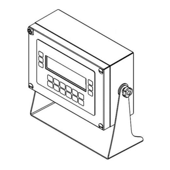
USE AND MAINTENANCE MANUAL Description of the terminal The DD700 terminal performs extremely accurate and reliable weighing operations. • Designed for industrial applications. • Supplied as per standard with weighing management metrologic software. • Body in ABS and stainless steel; available both in tabletop and wall-mounted versions. •... -
Page 8: Technical Features Of The Terminal
USE AND MAINTENANCE MANUAL 1.6 Technical features of the terminal Power supply Direct 12 VDC/4 A Through mains adaptor L+N+R 110 - 240 Vac (-15% … +10%) 1.8 A 50 - 60 Hz 60W Max Earth socket Equipotential for weighbridge Scales Total 1 analogue, 2 analogue multiplexing or 1 digital... -
Page 9: Declaration Of Conformity
USE AND MAINTENANCE MANUAL Communication ports USB Device USB Host Serial ports 1 RS232 - 1 RS232/ RS422 /RS485 Inputs - Outputs Memories Optional MPP board Expansions Slot for optional boards Optional boards Optional opto-isolated RS232, RS422/RS485 serial board PROFIBUS DP expansion board EtherNet/IP expansion board 0-10V / 4-20mA analogue output board WiFi 10/100 Mbit/sec board... -
Page 10: Overall Dimensions And Weight Of Terminal
USE AND MAINTENANCE MANUAL Overall dimensions and weight of terminal 1.8.1 Plastic version Figure 1.8-1 - Dimensions of plastic weighing terminal • Dimensions (expressed in mm): see figure 1.7.1. • Weight: 1.5 Kg 1.8.2 Tabletop stainless steel version Figure 1.8-2 - Dimensions of tabletop stainless steel weighing terminal •... -
Page 11: Wall-Mounted Stainless Steel Version
USE AND MAINTENANCE MANUAL 1.8.3 Wall-mounted stainless steel version Figure 1.8-2 - Dimensions of wall-mounted stainless steel weighing terminal • Dimensions (expressed in mm): see figure 1.7.3. • Weight: 4 Kg 1.8.4 Panel mount version Figura 1.8-4 - Dimensions of the weighing terminal panel mount •... -
Page 12: Instructions For The Disposal Of Electric Or Electronic Waste
USE AND MAINTENANCE MANUAL Instructions for the disposal of electric or electronic waste This symbol on the purchased weighing instrument indicates that: • This electric or electronic appliance cannot be disposed of as municipal solid waste. • It must be disposed of separately. •... -
Page 13: Safety Prescriptions
USE AND MAINTENANCE MANUAL SAFETY PRESCRIPTIONS Prohibited use The purchased instrument is a weighing system and has been designed and manufactured as such. It is intended primarily for weighing goods. • it is prohibited to use the terminal without taking the necessary precautions for its safe operation. •... -
Page 14: Delivery And Installation
USE AND MAINTENANCE MANUAL DELIVERY AND INSTALLATION Figure 3-1 – Bottom of terminal with connectors Key: 1. Slots for optional boards 2. Analogue scale 1 3. COM2 Port 4. COM1 Port 5. I/O terminal block 6. USB DEVICE port 7. USB HOST ports 8. - Page 15 USE AND MAINTENANCE MANUAL Figure 3-2 –Bottom of terminal with cable glands seen from outside (fig. above) and inside (fig. below) Key: 1. Slots for optional cards 2. Scale 1 3. COM2 Port 4. COM1 Port 5. I/O terminal block 6.
- Page 16 USE AND MAINTENANCE MANUAL Figura 3-3 – Bottom of terminal with connectors . Panel mount version Key: 1. Slots for optional cards 2. Scale 1 3. COM2 Port 4. COM1 Port 5. I/O terminal block 6. USB DEVICE port 7. USB HOST Ports 8.
-
Page 17: Installation
USE AND MAINTENANCE MANUAL Installation ATTENTION This terminal must be installed indoors, sheltered against atmospheric agents as it was not designed to withstand foul weather. 3.1.1 Tabletop installation Place the terminal on a stable surface (table or desk without wheels) so that the monitor is not exposed to direct light to avoid reflections, making sure it is stable and firmly resting on anti-slip feet. -
Page 18: Connection Diagram (Version With Connectors And Abs)
USE AND MAINTENANCE MANUAL 3.2.2 Connection diagram (version with connectors and ABS) To correctly connect the terminal to the electric mains, proceed as follows: • Connect the terminal to the power supply; • Plug in the terminal using the specific cable. Figure 3.2-1 –... -
Page 19: Connection Diagram (Dd700 Version With Cable Gland)
USE AND MAINTENANCE MANUAL Only for Panel Mounting is available a 12V power supply terminal block. Follow the diagram for proper connection. Connect one 12V power supply. Figura 3.2-3 – Vista Power Supply 12V Panel Mount Version 3.2.3 Connection diagram (DD700 version with cable gland) The installer is in charge of connecting the appliance to the electric power line. - Page 20 USE AND MAINTENANCE MANUAL DANGER Check that: • the voltage and frequency of the terminal's electric power line are as indicated on the stamped plate at the bottom of the terminal; • the socket the terminal is plugged into is earthed; •...
-
Page 21: Connecting Terminal To Weighing Platform
USE AND MAINTENANCE MANUAL Connecting terminal to weighing platform To connect the terminal to the weighing platform, a pre-wired cable is normally supplied. Its female connector must be inserted all the way into the male 9/15 pin (JBIL) connector at the bottom of the indicator. -
Page 22: Connection Diagram (With Platform)
USE AND MAINTENANCE MANUAL 3.3.1 Connection diagram (with platform) Figure 3.4-1 – Connection of the terminal to the scale Key: 1. Terminal with weight display. 2. Weighing platform or weighbridge. 3. Scale cable with 9/15 pin connector. 4. Scale inlet. 5. -
Page 23: Digital Scale Serial Connection
USE AND MAINTENANCE MANUAL 3.3.3 Digital Scale serial connection Female 15 pin cup connector. DESCRIPTION 485- EX + EX + EX - EX - 485+ EX - NC = Reserved not to connect The digital cells are connected by an RS485 serial transmission using a 6-conductor shielded cable. Pins with the same signal can be parallelised. -
Page 24: Serial Connections
USE AND MAINTENANCE MANUAL Serial connections 3.4.1 Serial output connection COM1 Female 9 pin cup connector. Key: NC = Reserved not to connect RX232 = Data reception TX232 = Data transmission CTS232 = Clear to send RTS232 = Request to send GND = Signals earth Figure 3.4-2 –... -
Page 25: Serial Output Connection Com2 In Rs422 Configuration
USE AND MAINTENANCE MANUAL in RS422 3.4.2 Serial output connection COM2 configuration Female 9 pin cup connector. Key: NC = Reserved not to connect RX422 +/- = Data reception TX422 +/- = Data transmission TERMIN = Termination resistance to connect to pin 6 Ri = Internal termination resistance on terminal NOTE : the free pins are reserved... -
Page 26: Rs232 Connections
USE AND MAINTENANCE MANUAL 3.4.3 RS232 connections ATTENTION Maximum operating conditions foreseen by standard RS232: Maximum transmission distance: 15 m Maximum voltage at ends: ± 12 Vdc For the connection towards external devices, it is recommended to use a shielded cable making sure to connect the shield to the metal part of the shell of the 9 pin connector. -
Page 27: Serial Output Connection Com2 In Rs485 Configuration
USE AND MAINTENANCE MANUAL 3.4.5 Serial output connection COM2 in RS485 configuration Female 9 pin cup connector. make the jumper between pin 6 and pin 8 to connect the termination resistance; this is performed on the first and last device connected one to another NC = Reserved not to connect DATA +/- = Two-way communication line... -
Page 28: Usb Connections
USB Device: the terminal has the "B" type connector (see figure 3.1 point 6). A DD700 device driver must be installed for them to be used. See the notes in the 09880079 folder in README for the installation instructions (the optional programme is provided by Società Cooperativa Bilanciai) -
Page 29: Input/Output Connection
USE AND MAINTENANCE MANUAL Input/Output Connection Input/output contacts are available on the back of the indicator on the I/O terminal block. Figure 3.51 – Terminal block pinouts GND OPTO DD700 OUTPUT 1 OUTPUT 2 Figure 3.5.2 – I/O terminal block connection diagram for Input/Output connection... -
Page 30: Input Connection
USE AND MAINTENANCE MANUAL 3.5.2 Input connection ATTENTION Electrical features Input: maximum voltage ≤ 5 Vdc maximum current ≤ 5 mA The inputs can be controlled by voltage-free contacts or by NPN transistors (common negative). 3.5.3 Output connection ATTENTION Electrical features Output: commutable voltage ≤... -
Page 31: Commands, Switch On And Off
USE AND MAINTENANCE MANUAL COMMANDS, SWITCH ON AND OFF On-off key To switch the terminal on when properly powered (connected to the electric mains by means of power supply), press the key on the front. Figure 4.1-1 – Switch-on Pressing the key again switches the terminal off. In this situation the terminal functions will be interrupted. - Page 32 USE AND MAINTENANCE MANUAL Figure 4.1-2 – Green LED on power supply Unplug the appliance to switch the system off completely.
- Page 33 USE AND MAINTENANCE MANUAL The following is a list of the weighing symbols with their meaning: Stable weight signal Indicates that the weight displayed is stable and can be printed and/or transmitted. "Center zero" signal Indicates that the weight detected by the platform is near zero, ranging within -1/4 + 1/4 of the division.
-
Page 34: Selection Display Signals To Display
USE AND MAINTENANCE MANUAL 4.1.1 Selection display signals to display Weight indication Below minimum set limit. Weight indication Within minimum and maximum set limits. Weight indication Above maximum set limit... -
Page 35: Metrologic Keys
USE AND MAINTENANCE MANUAL Metrologic keys Weight reset key Pressing this key resets the weight indication to zero only if the following conditions are met: • The weight value must be within the -1% ÷ +3% range of the capacity for terminals with obligation of metric verification and ±... -
Page 36: Alphanumerical Keys
USE AND MAINTENANCE MANUAL Alphanumerical keys Keys for entering numerical values and alphanumerical characters Decimals setting key Use this key to enter decimal values. Enter or confirmation key Press to confirm the operation. WARNING The function of the keys can change and the signalled by the specific indications on the display. On-off key On-off key Press alternately to switch on or off. -
Page 37: Using The Terminal
USE AND MAINTENANCE MANUAL USING THE TERMINAL General information 5.1.1 Using the keys for browsing the menus The numerical keys described in par. 5.1.3 and the customisable keys allow you to browse the programming menus. The menus can be entered from the normal display condition by selected item 2°F by pressing . -
Page 38: Entering Numerical Data (Editor)
USE AND MAINTENANCE MANUAL 5.1.2 Entering numerical data (Editor) Numerical values can be entered as follows: • select the function associated to the value you wish to set (preset tare, setups, range...); the selected function with the value currently stored will appear on the display; •... -
Page 39: Hotkeys
USE AND MAINTENANCE MANUAL The following is the list of characters associated to each key: Alphanumerical keys Characters , - + ; * / = % > < 0 . : ? ! ( )¿ ¡ ' (blank) 1 £ $ @ & ª º A B C 2 â... -
Page 40: Dd700 With External Usb Keyboard
USE AND MAINTENANCE MANUAL 5.1.5 DD700 with external USB keyboard DD700 is able to manage an external keyboard connected to the USB Host connector (type A) in the rear. Features • The keyboard type (country specific configuration) is selected in relation to the dd700 selected language. -
Page 41: Functioning Of Single Weighing Operation, Double Weighing, Sum Weighing, Load Extraction, Unload Extraction, Cpe Functioning, Manual Selector, Weight Check And Multi-Operator
USE AND MAINTENANCE MANUAL Functioning of Single weighing operation, Double weighing, Sum weighing, Load extraction, Unload extraction, CPE functioning, Manual Selector, Weight Check and Multi-Operator The type of terminal operation is set while being installed. The set operating mode is displayed when the terminal is switched on. 5.2.1 Single Weighing Operation (*) (***) The Single Weighing operation allows you to acquire the gross (or net) weight on the scale and to... -
Page 42: Input Operations
USE AND MAINTENANCE MANUAL the two input and output weights can be calculated on the second. Input operations With every incoming print, the terminal attributes and prints a code (Rcd code) which, if set before the second weighing operation, it recalls the initial data from the first weighing operation (weight, product code, client code and vehicle license plate). -
Page 43: Recovering Unused Rcd Codes
USE AND MAINTENANCE MANUAL The weight on the platform, the recalled RcD and the input weight are displayed. Press the key to activate the output operation. If necessary, cancel the operation by pressing 2°F before Also remember that once the RcD code is recalled, the product code and the plate and client code can also be modified using the PRODC, CLIENT and PLATE keys. -
Page 44: Input/Output Operation With Plate Data Recall
USE AND MAINTENANCE MANUAL Input/output operation with Plate Data Recall The RcD Plate code has a maximum of 10 alphanumeric characters that the operator manually assigns and which must be set before any input operation. Refer to the two previous points for input/output operation. In this case the reference key is not RCD but PLATE. -
Page 45: Preparing The List Of Preset Weights
USE AND MAINTENANCE MANUAL Preparing the list of preset weights As indicated previously, the preset weights can be associated with an RcP or RcP Plate code. The list must be prepared before carrying out any weighing operations. Proceed as follows: •... -
Page 46: Sum Weighing Operation
USE AND MAINTENANCE MANUAL 5.2.3 Sum Weighing operation The sum weighing function allows you to perform several weighing operations in sequence without discharging the scale, resetting the net weight after each operation. Going from one weighing operation to another is performed by pressing with the weight stable. -
Page 47: Load Extraction Operation (*) (***)
USE AND MAINTENANCE MANUAL 5.2.4 Load Extraction operation (*) (***) By default this function is not active and the relays are not programmed. See Advanced Manual During installation, request the appropriate I / O programming, or follow the instructions in the manuals. This operation allows, once selected and associated with the I / O devices, to perform simple dosages of a single component with two weight thresholds (two speeds), modifying the thresholds from the user menu. -
Page 48: Unload Extraction Operation (*) (***)
USE AND MAINTENANCE MANUAL 5.2.5 Unload Extraction operation (*) (***) By default this function is not active and the relays are not programmed. See Advanced Manual During installation, request the appropriate I / O programming, or follow the instructions in the manuals. This method of use is similar to the previous one, unlike the Load-in-Unload operation, the scale is normally a full silo and you want to extract material in cycles. -
Page 49: Manual Selection Mode Operation (**)
USE AND MAINTENANCE MANUAL 5.2.6 Manual selection mode operation (**) When set to operate in this mode, the terminal can manage up to 15 weight classes in order to classify the weighed product. 5.2.6.1 Classification display The classification appears on the display together with the weight. The time that the number range, to which the weight acquired during the weighing operation belongs, remains on the display, can be set as indicated in the advanced user manual. -
Page 50: Piece Counter Mode Operation (**)
USE AND MAINTENANCE MANUAL The terminal performs the controls on ranges always starting from the first and, once found, interrupts the search. In the event of ranges with equal values, the weight is only totalled on the first range found. If you wish to use a range as a discard range, you must use the last range available (15). -
Page 51: Multi-Operator Operation (**)
USE AND MAINTENANCE MANUAL • Heavy Total • Pieces Total 5.2.8 Multi-operator Operation (**) This is a shop scale operation. Several operators can perform weighing operation cycles simultaneously. For each operation, all the weighing data are stored and the total kept by operator code. When configured multi-operator mode, the terminal has the following functions available: 5.2.8.1 Operator Archive The operator archive consists of:... -
Page 52: Print Archive
USE AND MAINTENANCE MANUAL • • Number of Weighing Operations 5.2.8.3 Print Archive The operator archive consists of: • Print Number (search key) • Product code • Generic code • Date • Time • Gross • Tare1 • Tare2 • N. -
Page 53: Cancellation Of Weighing Operation
USE AND MAINTENANCE MANUAL • Generic code • Gross • Tare • Tare1 • Tare2 • N. of packs • Closure • Gross Total • Tare Total • Net Total • N° Weighing operations • Text at foot of page •... -
Page 54: Weight Check Operation (**)
USE AND MAINTENANCE MANUAL 5.2.9 Weight Check Operation (**) This function allows you to verify whether the weight of the product on the scale is within, higher or lower than a preset range of values. A coloured LED bar displays its range. It is possible to associate the weighing range to a product code. - Page 55 USE AND MAINTENANCE MANUAL In range ( between lower limit and upper limit ) RED 1 YELLOW 1 YELLOW 2 YELLOW 3 GREEN 1 GREEN 2 YELLOW 1 YELLOW 2 YELLOW 3 In range ( between lower limit and upper limit ) RED 1 YELLOW 1 YELLOW 2 YELLOW 3 GREEN 1 GREEN 2...
-
Page 56: Weighing Limit Entry
USE AND MAINTENANCE MANUAL 5.2.9.2 Weighing limit entry To enter the weighing limits, press the shortcut key CHECK and select one of the following modes: ...>ACQUISITION>TARGET Place a sample piece on the scale. Press the TARGET button and the acquired weight will become the central value of the weighing range: the lower limit will set to 20 divisions less than the target while the upper limit will set to 20 divisions more than the target. -
Page 57: User Menu
USE AND MAINTENANCE MANUAL User menu Below is the user menu tree illustrated to the 3rd level. For details see the paragraphs below. 5.3.1 User menu tree MANAGEMENT OF COMMON FUNCTIONS IN OPERATIONS (SINGLE WEIGHING OPERATION, DOUBLE WEIGHING, LOAD AND UNLOAD EXTRACTION (*) (***) Data management Code Management... - Page 58 USE AND MAINTENANCE MANUAL Partial Total Product Code Total (product code total archive present) Generic Code Total (generic code total archive present) MPP operation (MPP if device enabled) De-activated With memory Display Contrast Memory status Reprint Date Time Printer cut Weighing range (Multi-division /Multi-extension with weighing fields management) Automatic Extension w1...
- Page 59 USE AND MAINTENANCE MANUAL MANAGEMENT OF COMMON FUNCTIONS IN OPERATIONS (CPE, MANUAL SELECTOR, WEIGHT CHECK, MULTI-OPERATOR) (**) Data management Code Management Product Code Generic Code Product Code List Range Range 01 Range 02 Range 11 (If optional board present) Range 12 (If optional board present) Range 13 (If optional board present) Range 14 (If optional board present) Range 21 (If optional board present)
- Page 60 USE AND MAINTENANCE MANUAL Reprint Date Time Scale selected (Multi-scale) Printer cut Weighing range (Multi-division /Multi-extension with weighing fields management) Automatic Extension w1 Extension w2 Extension w3 Auto-sswitch off (OPT) External battery voltage Battery charge time Battery charge Lighting High intensity Low intensity Temporary high intensity Activate buzzer...
- Page 61 USE AND MAINTENANCE MANUAL Plate Code (only present if RCD/RCP numerical) Plate total RCD code or RCD PLATE Code RCD code list or RCD PLATE Code RCP code or RCP PLATE Code RCP code list or RCP PLATE Code Display Double Weighing operation LOAD/UNLOAD EXTRACTION (*) (***) Display...
-
Page 62: Modify Date And Time
USE AND MAINTENANCE MANUAL 5.3.2 Modify date and time Follow the path: ...>MENU>Date Time (DATIME hotkey). To quickly change summer time, use + or - 1 hour, otherwise use the entry CHANGE. 5.3.3 Weight display This can be customised depending on how you wish the weight on the scale to be displayed. It depends on the type of operation set during installation. -
Page 63: Memory Status
USE AND MAINTENANCE MANUAL Tare: tare value + unit of measurement will light up. The indications • If the tare is preset and multiple tares were not set: Tare C: preset tare value + unit of measurement The indications and PT will light up. WARNING The wording C Tare which is the tare viewed on the display is an "encoded"... -
Page 64: Reprint
USE AND MAINTENANCE MANUAL ATTENTION The terminal could need a few minutes to recovery the memory. Do not switch the terminal off during this operation to avoid losing stored data. 5.3.5 Reprint 5.3.28.1 See par. 5.3.6 Diagnostics (only for digital scale) This item in the user menu is only available when the digital cells have errors and makes it possible to find the cause that generated the error. -
Page 65: Setting Output As Range (If Enabled)
USE AND MAINTENANCE MANUAL 5.3.10 Setting output as Range (if enabled) The outputs available in Range mode can be used. The output is activated when the weight or number of pieces (CPE) (**) is within the range; this interval is set by following the path: ...>MENU>Data Management>Range (RANGE hotkey). - Page 66 USE AND MAINTENANCE MANUAL ...>MENU>Data Management>Codes Management>Product Code (PROCOD hotkey). Enter the product code and the matching alphanumerical description as explained respectively in par. 5.1.2 and par. 5.1.3. Setting the product code at 0 (zero) during weighing operations excludes any totalling operation.
-
Page 67: Product Codes List
USE AND MAINTENANCE MANUAL 5.3.13 Product codes list Following the path: ...>MENU>Data Management>Codes Management>Product Code List allows you to view the description of the code by recalling the product code in question. To recall the product code, press PRODC, type in the numerical code and press to confirm. -
Page 68: Preset Tares List
USE AND MAINTENANCE MANUAL 5.3.15 Preset tares list Following the path: ...>MENU>Data Management>Preset tares>Preset Tares List displays the value of the corresponding tare by recalling the tare code in question. To recall the tare code, press TAREC, type in the numerical code and press to confirm. -
Page 69: Totals Management
USE AND MAINTENANCE MANUAL 5.3.18 Totals Management The terminal allows you to total the weighing data associated to the different codes managed. Totalling consists of adding the weight value to the sum of the previous weight values, increasing the number of weighing operations by one. -
Page 70: Scale Selection (**) (***)
USE AND MAINTENANCE MANUAL ...>MENU>Totals Management>Client Total (double weight) (CLTOT hotkey) • PRINT produces the print of the selected total • SUMM produces the print of all codes • RESET resets the total at zero • CLIENT allows you to shift to another client code 5.3.19 Scale Selection (**) (***) When there are two scales connected, this allows you to select which must work. -
Page 71: Lighting
USE AND MAINTENANCE MANUAL 5.3.20 Lighting ...>MENU>Lighting or ILLUM hotkey Allows you to manage the display lighting mode: • HIGH INTENSITY The display works at maximum light intensity • LOW INTENSITY The display works at minimum light intensity • TEMPORARY HIGH INTENSITY The display is lit at maximum intensity For 10 seconds if: •... -
Page 72: Printer Cut
USE AND MAINTENANCE MANUAL To access this menu, follow the path: ...>MENU>Weighing operation (PRINT hotkey). 5.3.25 Printer Cut This function is only available if a printer managing the cut is enabled (STB80/Q3/Q3X/STB112/TMU220/STB2080) and cuts the paper. To access this menu, follow the path: ...>MENU>Printer cut (CUTPAP hotkey). - Page 73 USE AND MAINTENANCE MANUAL • “FDB_MAP.TXT” Some are optional if you use an other serial: • Save archives (Backup) and the file to be trasferred • Recover archives (Restore) and the file to be transferred Selecting "Recover configuration”, the terminal check if there are any files on the USB stick; selecting them you can upload them to the terminal.
- Page 74 USE AND MAINTENANCE MANUAL Figure 5.3.27 –Connection between PC and terminal for Backup-Restore The archives that can be exported (Backup) are: Product Code Client Code Tare Code Rcp/Rcp Plate (*) (***) Product Code Total Client Code Total (*) (single weight) General Code Total (double weight) Plate Total (*) (***) Printed data string...
-
Page 75: Printing Weighing Data
USE AND MAINTENANCE MANUAL • On the terminal, when the transfer is complete, and if you have selected the Back all function, press ESC to go back to normal weight viewing conditions; if you have selected the Backup function, select any other archive that needs to be transferred and repeat the procedure. At the end of these operations, the binary files of the archives will be in the designated directory on the PC, for example PRODARC for the commodities archive. -
Page 76: Reprinting Weighing Data
USE AND MAINTENANCE MANUAL If enabled, some data can be printed as a barcode, such as: product code and net weight, net weight only, generic code + net weight, client etc... Printing can be customised by using a PC and a specific composition program: contact the supplier for further information. -
Page 77: Product Code Totals Archive (**)
USE AND MAINTENANCE MANUAL 5.3.32 Product Code totals Archive (**) The totals archive for the product code consists of: • code • net total in tare tolerance • weighing operations total in tolerance • net total under tolerance • weighing operations total under tolerance •... -
Page 78: Automatic Print/Transmission (**)
USE AND MAINTENANCE MANUAL 5.3.35 Automatic print/transmission (**) The terminal can be configured in the setup menu for automatic printing/transmission in 3 different modes (see advanced user manual). • Print stable weight(in range) Printing is carried out automatically if the weight is within the acceptance range and a stable weight condition is detected. -
Page 79: Options
USE AND MAINTENANCE MANUAL OPTIONS MPP memory expansion boards Terminals equipped with the MPP option (permanent weight memory) are characterised by the possibility of storing the weight data of each individual weighing operation in a permanent memory and of transmitted the value to an external peripheral device together with an ID code automatically assigned by the terminal. -
Page 80: Mpp Deactivation
USE AND MAINTENANCE MANUAL 6.1.3 MPP deactivation When using the weighing system, it could be necessary not to transfer or store the weighing data in the MPP memory. In that case, to deactivate it, type: ...>MENU>MPP Operation> De-activated To re-enable MPP: ...>MENU>MPP Operation>... -
Page 81: Analogue Output Board
USE AND MAINTENANCE MANUAL Analogue output board The connector has an analogue alternative output in 0-10 V and 4-20 mA formats separated galvanically. The connection diagram is displayed in the table below. Pin n° Signal Common 4-20 mA output 0-10 V output ATTENTION Technical features: Resolution = 10000 dots... - Page 82 USE AND MAINTENANCE MANUAL RX422 +/- = Data reception RX232 = Data reception TX422 +/- = Data transmission TX232 = TERMIN data transmission = Termination resistance to connect to pin6 NC = Reserved not to connect GND = Signals earth connection Ri = Internal termination resistance on terminal Figure 6.3.1 –...
-
Page 83: Optional 4 Input/ 4Output Board
USE AND MAINTENANCE MANUAL Optional 4 Input/ 4Output board OUTPUT OptoMOS voltage-free contacts Vmax 24 Vac/Vdc Imax 190mA . They have separate common connections: - COMOUT1:pin1, common for OUT from 1 to - COMOUT2:pin6, common for OUT from 3 to INPUT Galvanic insulation input Vmax 24Vdc. -
Page 84: Ethernet Board 10/100 Mbit
USE AND MAINTENANCE MANUAL Ethernet Board 10/100 Mbit Consult the specific expansion board manual. Profibus DP Board Consult the specific expansion board manual. Ethernet/IP Board Consult the specific expansion board manual. Level (**) Inclination sensor used with PTE/PTM. -
Page 85: Troubleshooting
USE AND MAINTENANCE MANUAL TROUBLESHOOTING If the suggested remedy does not solve the problem, contact Assistance Service. Malfunctions PROBLEM CAUSE REMEDY The terminal No power Check that power arrives at does not switch on the mains outlet socket. Check that the mains lead is correctly plugged in. -
Page 86: Error Messages
USE AND MAINTENANCE MANUAL Error Messages PROBLEM CAUSE REMEDY Overload The scale is Reduce the weight to a value overloaded. below the maximum scale capacity. Underload The balance is If on completion of the operation negative at least 20 the display shows a value other divisions. -
Page 87: Memory Fill Message
DD700 USE AND MAINTENANCE MANUAL Weight not valid The scale is in See conditions for correct negative weight printing in par. 5.3.28 or overload condition and the printer does not print Printer error Printer switched Check printer is connected off or and switched on disconnected The last line at... - Page 88 DD700 USE AND MAINTENANCE MANUAL...
Need help?
Do you have a question about the DD700ic and is the answer not in the manual?
Questions and answers