
Related Manuals for Bilanciai PRM-A


Summary of Contents for Bilanciai PRM-A
- Page 1 USE AND WARNING INSTRUCTIONS TRANSLATION OF THE ORIGINAL INSTRUCTIONS WEIGHING PLATFORM PRM-A MANUAL CODE: 81320089 CLIENT YEAR OF MANUFACTURE: 2023 EDITION: 08/2023 - REVISION: 01...
- Page 2 INFORMATION The manufacturer is not liable for damage to property or persons caused by failure to comply with the instructions in this manual. COPYRIGHT © 2023 Soc. Coop. Bilanciai Campogalliano...
-
Page 3: Table Of Contents
Use and warning manual CONTENTS 1. IDENTIFICATION ....................6 MANUFACTURER IDENTIFICATION ....................... 6 MACHINE IDENTIFICATION..........................6 IDENTIFICATION PLATE ............................. 7 CONTENT OF THE EU DECLARATION OF CONFORMITY ..............9 REFERENCE DIRECTIVES ........................... 10 2. PRELIMINARY INFORMATION ............... 11 RECIPIENTS ................................11 SUPPLY AND STORAGE ............................ - Page 4 WEIGHING PLATFORM - PRM-A TECHNICAL DATA ............................. 28 4.4.1 OVERALL DIMENSIONS MAIN COMPONENTS ............................31 4.5.1 ABOVE GROUND VERSION 4.5.2 PIT-MOUNTED VERSION INSTRUMENT DESCRIPTION .......................... 36 WORK PROCESS DESCRIPTION ........................37 OPTIONAL ACCESSORIES ..........................37 5. TRANSPORT AND COMMISSIONING ............39 PACKAGING ................................
- Page 5 Use and warning manual LIST OF ANNEXES.............................. 65...
-
Page 6: Identification
WEIGHING PLATFORM - PRM-A 1. IDENTIFICATION 1.1 MANUFACTURER IDENTIFICATION Soc. Coop. Bilanciai Campogalliano MANUFACTURER Via S. Ferrari 16 - 41011 Campogalliano (MO) ADDRESS Italy Tel. +39 059 893611 Fax +39 059 527079 CONTACTS info@coopbilanciai.it www.coopbilanciai.com 1.2 MACHINE IDENTIFICATION NAME WEIGHING PLATFORM... -
Page 7: Identification Plate
Use and warning manual 1.3 IDENTIFICATION PLATE The instrument is equipped with an identification plate. The identification plate is positioned as shown in the figure below. The instrument's identification details can be found on the identification plate. 1. Instrument precision class. 2. - Page 8 WEIGHING PLATFORM - PRM-A...
-
Page 9: Content Of The Eu Declaration Of Conformity
Use and warning manual 1.4 CONTENT OF THE EU DECLARATION OF CONFORMITY... -
Page 10: Reference Directives
WEIGHING PLATFORM - PRM-A 1.5 REFERENCE DIRECTIVES The instrument supplied by the manufacturer complies with Directive 2014/31/EU EEC. The manufacturer places instrument on the market with: CE Marking Document drawn up according to point 1-A of annex II of the EU Declaration of Conformity "Machinery Directive"... -
Page 11: Preliminary Information
2. PRELIMINARY INFORMATION 2.1 RECIPIENTS The manual is intended for operators in charge of using and managing the instrument throughout its service life. The manual contains topics that refer to the correct and safe use of the instrument. The manual is an integral part of the instrument and must accompany it whenever it is relocated or resold. The user must keep the manual intact for reference throughout the life of the instrument. -
Page 12: Glossary
2.5 GLOSSARY The following table explains the terms and abbreviations used in this manual: TERM DEFINITION Derived from the words ATmosphèresand EXplosibles. This is the conventional name for two European Union (EU) directives: 2014/34/EU for the regulation of equipment intended for use in •... - Page 13 TERM DEFINITION The set of provisions or measures that are also necessary according to the particular nature of the work, experience and technique, in order to avoid PREVENTION risks or reduce the probability of their occurrence. Defence against what could cause harm. Element that interposes itself between who may suffer harm and what may cause it due to hazards that cannot be reasonably eliminated or risks that cannot be sufficiently reduced during design.
-
Page 15: Operator Qualifications
2.6 OPERATOR QUALIFICATIONS The table below shows the skills and qualifications of the operators assigned to the various tasks: JOB DESCRIPTION DEFINITION User personnel, trained and able to: Use the tool for production purposes, for the activities for which it was •... - Page 16 JOB DESCRIPTION DEFINITION Qualified technician capable of: Carrying out preventive/corrective maintenance on all electrical parts • of the instrument subject to maintenance or repair. Operating in the presence of voltage inside electrical panels, junction • boxes, control equipment etc. (only if he/she is a qualified person - PEI).
-
Page 17: Safety Messages Used Within The Manual
2.7 SAFETY MESSAGES USED WITHIN THE MANUAL Safety messages in the manual are used to emphasise important information. The following table describes the safety messages used: SYMBOL MESSAGE DEFINITION Instruction referring to an imminently hazardous situation which, if not avoided, will cause instantaneous death or DANGER serious or permanent damage to health. -
Page 18: Personal Protective Equipment
2.8 PERSONAL PROTECTIVE EQUIPMENT Personnel working near the instrument must comply with the general accident prevention regulations and use the personal protective equipment (PPE) required for each individual operation. The following table shows the P.P.E. that may be required for the different procedures: SYMBOL DESCRIPTION Duty to use protective or insulating gloves. -
Page 19: Warranty
2.9 WARRANTY INFORMATION The full warranty clauses are incorporated in the sales contract. Contact the Manufacturer for warranty information if in doubt. -
Page 20: Safety Devices
3. SAFETY DEVICES 3.1 NOISE The noise exposure level of personnel is less than 80 dB, during the instrument's operating cycles. The actual noise level of the instrument during operation at the site of use is different from the measured value. -
Page 21: Residual Risks
The efficiency of the solutions adopted on the instrument may be compromised in case of improperly performed maintenance or replacement of electrical parts. 3.4 RESIDUAL RISKS The instrument is designed to ensure the essential safety requirements for the operator. Safety was integrated into the design and construction of the instrument as far as possible. However, there are still risks that operators must be protected from, especially when during: Transport and installation. -
Page 22: Safety Pictograms
3.5 SAFETY PICTOGRAMS A series of safety pictograms are applied on the machine to identify points and areas where residual risks remain. Safety was integrated into the design and construction of the instrument as far as possible. INFORMATION Do not remove the pictograms from the machine. The user must replace pictograms that are removed or illegible. - Page 23 PAGE LEFT INTENTIONALLY BLANK...
-
Page 24: Instrument Description
4. INSTRUMENT DESCRIPTION 4.1 INTENDED USE The instrument is designed to be used for the following purposes: ENVIRONMENT OF OPERATION ALLOWED NOT ALLOWED Pallets with features Any other use and/or Non-automatic listed under Technical product other than Industrial weighing of: Data. -
Page 25: Obligations And Prohibitions
The manufacturer accepts no liability in the event of improper use of the instrument. 4.3 OBLIGATIONS AND PROHIBITIONS 4.3.1 USERS’ OBLIGATIONS The user (contractor or employer) must: Take the operators’ skills and conditions into account in relation to their health and safety. •... - Page 26 Immediately report deficiencies, malfunctions or the absence of required safety devices to the • employer, manager or supervisor.
-
Page 27: Prohibitions Of Operating Personnel (Operators/Maintenance/Technicians)
4.3.3 PROHIBITIONS OF OPERATING PERSONNEL (OPERATORS/MAINTENANCE/TECHNICIANS) Personnel operating the instrumentmust not : Use the instrument on other machines or moving installations. • Place the instrument even temporarily in a transit area in order not to compromise its structural • integrity. Overload the instrument, but respect its maximum capacity (see CHAP.4 - TECHNICAL DATA). -
Page 28: Technical Data
4.4 TECHNICAL DATA TECHNICAL DATA Load capacity From 600 to 3000 kg Load cells 4 stainless steel cells INFORMATION Refer to the wiring diagram enclosed with this manual for more information on the instrument's electrical system. PRODUCT DATA THAT CAN BE PROCESSED WITH THE INSTRUMENT WEIGHED Pallets for transporting various contents. -
Page 29: Overall Dimensions
4.4.1 OVERALL DIMENSIONS CAPACITY DIVISION MODEL DIMENSIONS (mm) (kg) PRM-A 150.125 1500 1250 1500 1250 1500 PRM-A 150.125 1500 1250 2000 PRM-A 150.125 1000 1500 1250 3000 PRM-A 150.125 2000 1250 1500 PRM-A 200.125 2000 1250 2000 PRM-A 200.125 1000... -
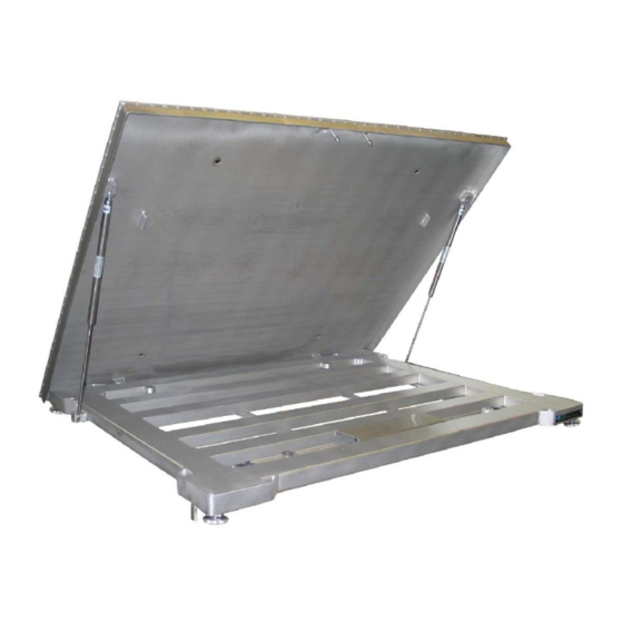
Page 31: Main Components
4.5 MAIN COMPONENTS 4.5.1 ABOVE GROUND VERSION The instrument consists of the following main components: POS. COMPONENT Weighing platform. Weighing platform access platform/ramp. Terminal for connection to metal masses. - Page 32 Levelling control air bubble. Loading cell. Connection cable to the electronic terminal. Supporting foot.
- Page 33 Junction box. Lifting handle...
-
Page 34: Pit-Mounted Version
4.5.2 PIT-MOUNTED VERSION The instrument consists of the following main components: POS. COMPONENT Counterframe to be integrated into the masonry (foundation). Terminal for connection to metal masses. Levelling control air bubble. Loading cell. - Page 35 Connection cable to the electronic terminal. Supporting foot. Junction box. Lifting handle...
-
Page 36: Instrument Description
4.6 INSTRUMENT DESCRIPTION The instrument is designed for weighing goods. Weight is measured using four loading cells (stainless steel with IP 67 rating). These cells are anchored to the one-piece structure of the instrument and rest on the ground via four levelling feet directly connected to the cells. -
Page 37: Work Process Description
4.7 WORK PROCESS DESCRIPTION The following table describes the work process of the instrument: STEP DESCRIPTION Place the load to be weighed on the instrument platform. Display the weight on the terminal (in 'single scale' or 'multi division' version). Remove the load from the platform. 4.8 OPTIONAL ACCESSORIES The instrument can be equipped with the following optional parts: Multi-division version. - Page 38 PAGE LEFT INTENTIONALLY BLANK...
-
Page 39: Transport And Commissioning
5. TRANSPORT AND COMMISSIONING 5.1 PACKAGING The instrument is shipped by the manufacturer from the production plant to the user customer's plant, unless otherwise agreed between the parties. The packaging of the instrument is carried out as follows: Normal protective packaging for short and medium distances. •... -
Page 40: Transport And Handling
Risk of damage to the instrument. Handle the instrument with extreme care, especially if it is unpacked. 5.2 TRANSPORT AND HANDLING 5.2.1 UNIT AND WEIGHT DIVISION TABLE The instrument must be transported in one piece. GROSS MODEL DIMENSIONS (mm) WEIGHT WEIGHT (kg) (kg) -
Page 41: Lifting And Handling Operations
5.2.2 LIFTING AND HANDLING OPERATIONS The instrument is designed to be transported in vehicles prepared for the purpose. Refer to the section Loading/Unloading from Transport vehicle for more information on the means of transport to be used. The instrument can also be lifted and moved by a forklift truck. INFORMATION Only a lifting equipment driver may carry out the lifting and handling of the instrument. - Page 42 5.2.2.1 TRANSPORT WITH A FORKLIFT TRUCK TRANSPORT WITH FORKLIFT TRUCK Appointed personnel Driver of lifting equipment qualification Required P.P.E. Means to be used Forklift truck Weight Variable depending on version Tools to be used None To transport with a forklift truck, proceed as described below: STEP ACTION Position the forks of the forklift under the base of the instrument.
- Page 43 5.2.2.2 TRANSPORT WITH LIFTING CRANE TRANSPORT WITH LIFTING CRANE Appointed personnel Driver of lifting equipment qualification Required P.P.E. Means to be used Lifting crane Weight Variable depending on version Tools to be used Bands - chains and eyebolts To lift with a crane, proceed as described below: STEP ACTION Attach the lifting ropes or chains to the specially provided eyebolts.
- Page 44 Check that the load is correctly balanced by lifting it slightly off the ground and checking that it is horizontal.
-
Page 45: Installation And Commissioning
5.3 INSTALLATION AND COMMISSIONING 5.3.1 SET-UPS TO BE PROVIDED BY THE CUSTOMER As a general rule, without prejudice to any other contractual agreements, the Customer shall be responsible for setting up: The power supply for the machine, including the earthing system, according to the characteristics •... -
Page 46: Installation Place
Ambient lighting > 350 lux Standing surface Concrete industrial floor WARNING Ensure that the surface that the instrument is installed on is flat, solid and able to withstand the expected loads. 5.3.3 INSTALLATION PLACE For installation, an area suitable for the size of the machine and the lifting equipment used must be provided, paying attention to any obstacles (other machines, walls or the like) along the route to be covered by the handling equipment. - Page 47 STEP ACTION Screw the terminal (4) to any metal conductive parts in the system. INFORMATION Place the remaining cable inside the platform profiles, avoiding excessive bends and metal parts that could damage or cut it. STEP ACTION Connect the terminal connection cable. NOTE: Depending on the type of electronic terminal, the cable can be: Cylindrical type (7).
- Page 48 Position the terminal no further away than as allowed by the instrument's connection cable. If necessary, request a new cable from the Manufacturer. STEP ACTION Connect the instrument to the factory power supply. NOTE: See the Connections paragraph. • CAUTION Risk of damage to the instrument.
-
Page 49: Installation And Levelling - Pit-Mounted Version
5.3.5 INSTALLATION AND LEVELLING - PIT-MOUNTED VERSION To correctly install and level the instrument, follow the procedure below: STEP ACTION Prepare a suitable work area: For the power supply requirements of the instrument. • For the space required for loading and unloading the product. •... - Page 50 STEP ACTION Place the connection cable to the terminal in the terminal compartment (1). NOTE: The excess part of the cable must be housed in the lower part of the instrument.
-
Page 51: Connections
5.4 CONNECTIONS The instrument must be connected to the User's supply network in order to be used. Guaranteeing the required connection characteristics is the User’s responsibility. 5.4.1 ELECTRICAL CONNECTION WARNING Electrocution hazard. The main switch on the electrical panel must be in the 0-OFF position before proceeding with the electrical connection of the instrument. -
Page 52: Controls And Use
6. CONTROLS AND USE The instrument requires the continuous presence of a single operator for its operation. 6.1 CONTROLS The following table lists the instrument control systems: POS. ELEMENT ELECTRONIC TERMINAL INFORMATION... - Page 53 Refer to the 'Electronic Terminal Manual' enclosed with this manual for all information regarding the operation of the instrument.
-
Page 54: Operational Procedures
6.2 OPERATIONAL PROCEDURES 6.2.1 PRELIMINARY CHECKS Carry out the following checks before commissioning the instrument: Check the presence of all safety devices. • Check the operation of the safety devices. • Check that there are no obstructions and/or obstacles around the instrument and in the transit •... -
Page 56: Maintenance
7. MAINTENANCE DANGER Risk of serious damage to the health of personnel. Perform the procedures described in this chapter only with the instrument switched off. Turn the master switch to 0-OFF. Wear the prescribed PPE for each procedure. Maintenance of the instrument includes the inspection, checking, control, adjustment and replacement required as a result of normal use of the instrument. - Page 57 Instrument maintenance work is divided, from an operational point of view, into two main categories: Operations carried out by the maintenance technician in a preventive manner, to ensure the proper functioning of the instrument over time. Routine maintenance includes the following: Inspection •...
-
Page 58: Placing The Instrument In Maintenance Mode
7.1 PLACING THE INSTRUMENT IN MAINTENANCE MODE DANGER Risk of serious damage to the health of personnel. Follow the procedure described in this section before performing any maintenance work. INFORMATION Refer to the 'Controls' paragraph of this manual for the location of the instrument controls. -
Page 59: Routine Maintenance
7.2 ROUTINE MAINTENANCE INFORMATION Only personnel defined as 'Maintenance Technician' may perform routine maintenance operations on the instrument. Refer to the 'Operator qualifications' paragraph of this manual. Routine maintenance includes the following: Checking the mechanical conditions of the instrument. • Cleaning the instrument. -
Page 60: Cleaning
7.2.1 CLEANING DANGER Risk of serious damage to the health of personnel. Follow the procedure described in the paragraph on 'Placing the instrument in maintenance mode' before proceeding. CAUTION Risk of damage to the instrument's electrical components. Do not direct jets of water or liquids onto the electrical parts of the instrument. INFORMATION Comply with the regulations in force in the country of use on washing water treatment. - Page 61 7.2.1.1 GENERAL CLEANING OF THE INSTRUMENT To perform a general cleaning of the instrument, proceed as described below: STEP ACTION Clean the instrument carefully with a dampened cloth Raise the platform (1). NOTE: Use the handle to lift the platform. Check for dirt under the platform and remove it.
-
Page 62: Extraordinary Maintenance
7.3 EXTRAORDINARY MAINTENANCE INFORMATION Only personnel defined as 'Maintenance technician' may carry out extraordinary maintenance operations on the instrument. Refer to the 'Operator qualifications' paragraph of this manual. When extraordinary maintenance work is required, the User's regular maintenance personnel must: Check the condition of damaged or malfunctioning units. -
Page 63: Decommissioning And Disposal
8. DECOMMISSIONING AND DISPOSAL INFORMATION Only authorised personnel may carry out the decommissioning and disposal of the instrument. 8.1 DECOMMISSIONING Decommissioning is necessary in case of prolonged non-use of the instrument. To decommission the instrument , proceed as described below: STEP ACTION Turn the master switch to 0-OFF. -
Page 64: Disposal
8.2 DISPOSAL INFORMATION Dispose of instrument components in accordance with the regulations of the country of demolition. The instrument consists mainly of the following materials: MATERIAL DISPOSAL PROCEDURE PLASTIC Dismantle and dispose of separately. Dismantle and collect separately. IRON It must be recycled through the appropriate collection centres. Dismantle and collect separately. -
Page 65: Annexes
STEP ACTION Sort machine components for separate disposal. 9. ANNEXES 9.1 LIST OF ANNEXES The following table lists the annexes that form an integral part of this manual: CODE ANNEX SUB-SUPPLIERS' MANUALS OPERATOR PANEL MANUAL... - Page 66 PAGE LEFT INTENTIONALLY BLANK...
- Page 67 PAGE LEFT INTENTIONALLY BLANK...
Need help?
Do you have a question about the PRM-A and is the answer not in the manual?
Questions and answers