Table of Contents
Advertisement
Quick Links
Advertisement
Table of Contents

Subscribe to Our Youtube Channel
Related Manuals for Unic STELLA EPIC 3


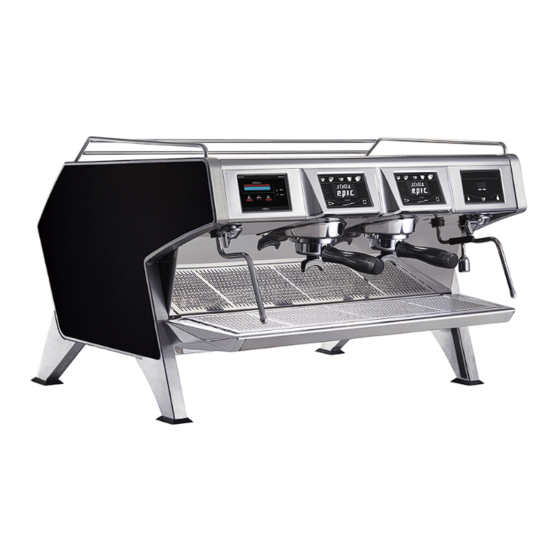
Summary of Contents for Unic STELLA EPIC 3
- Page 1 STELLA EPIC User manual * SE9020- 2021.01 *Original instructions...
- Page 2 Installation diagram EPIC 2 50 mini 50mini 50 mini AVANT / FRONT...
- Page 3 Installation diagram EPIC 3 50 mini 50 mini 50 mini AVANT / FRONT...
- Page 4 DO = Drain outlet CWI = Cold water inlet G 3/8″ EI = Electricity inlet...
- Page 5 Foreword The installation, use and maintenance manual (hereinafter Manual) provides the user with information necessary for correct and safe use of the machine (or “appliance“). The following must not be considered a long and exacting list of warnings, but rather a set of instructions suitable for improving machine performance in every respect and, above all, preventing injury to persons and animals and damage to property due to im- proper operating procedures.
-
Page 6: Table Of Contents
Contents A SAFETY INFORMATION ......................... 7 General information ........................7 General safety ..........................7 Personal protection equipment ......................8 Transport, handling and storage ...................... 8 Installation and assembly ....................... 9 Water connection.......................... 9 Electrical connection ........................9 Use ............................10 appliance cleaning and maintenance .................... -
Page 7: Asafety Information
SAFETY INFORMATION General information To ensure safe use of the appliance and a proper understanding of the manual it is necessary to be familiar with the terms and typographical conventions used in the documentation. The following symbols are used in the manual to indicate and identify the various types of hazards: WARNING Danger for the health and safety of operators. -
Page 8: Personal Protection Equipment
Personal protection equipment Summary table of the Personal Protection Equipment (PPE) to be used during the various stages of the machine's service life. Stage Protective Safety Gloves Glasses Safety garments footwear helmet — ● ○ — ○ Transport — ● ○... -
Page 9: Installation And Assembly
Installation and assembly • The installation must be carried out by a specialised personnel. • Follow the installation instruction supplied with the appliance. • Do not install a damaged appliance. Any missing or faulty parts must be replaced with original parts. •... -
Page 10: Use
isolation fault in the TN or TT systems or, for IT systems, the use of isolation controllers or differential current protection devices to activate automatic power disconnection (an isolation controller must be provided for indicating a possible first earth fault of a live part, unless a protection device is supplied for switching off the power in case of a such a fault. -
Page 11: Machine Disposal
A.12 Machine disposal • Work on the electrical equipment must only be carried out by a specialised personnel, with the power supply disconnected. • Dismantling operations must be carried out by specialised personnel. • Make the appliance unusable by removing the power cable and any compartment closing devices, to prevent the possibility of someone becoming trapped inside. -
Page 12: End Of Use
Risk a combination of probabilities and risks of port personnel. injury or harm to health in a hazardous Manufacturer UNIC SAS or any other service centre situation. authorised by UNIC SAS. Protection safety measures consisting of the use of Operator for... -
Page 13: Machine And Manufacturer's Identification Data
CE marking Any supplements to the installation, use and maintenance manual the Customer receives from the Manufacturer will form UNIC, Z.I. 4ème rue - manufacturer an integral part of the manual and therefore must be kept B.P. 425, 06515 together with it. -
Page 14: Dnormal Use
NORMAL USE Characteristics of personnel enabled to Operator qualified for normal machine operate on the machine The Customer is responsible for ensuring that persons Must have at least: assigned to the various duties: • knowledge of the technology and specific experience in operating the machine;... -
Page 15: Switching On The Heating
• Switch the machine off and on again: switch the main switch “Password“ To access the main menu, it is necessary to to 0 and then back to 1 enter a Level 1 or Level 2 code. If the USB dongle is inserted: click on “OK“... -
Page 16: Service Keyboards
4. Large cup(s) icon, number of coffee according to the engaged filter holder (1 or 2 cups) 5. Self mod icon (automatic start of coffee cycle) 6. Display 7. Stop icon (free mode) 8. Pre-infusion icon (free mode) 9. Start icon (free mode) 10. -
Page 17: External Cleaning
Step 3 Step 6 The progress bar (blue) indicates the number of cycle finished The BTA displays the message “groups cleaning completed”, confirm by press Ok button Step 4 “Remove the plug, reinsert the filter and press CONFIRM” External cleaning Description of the rinsing cycle: (EVX +PUMP) = ON for 45 Steam output tube: seconds... -
Page 18: Isteamair Option
disposed of in compliance with current regulations in the disposed of in order to prevent possible negative consequen- country of use. ces for the environment and the human health. All metal parts are in stainless steel (AISI 304) and removable. Regarding the recycling of this product, please contact the Plastic parts are marked with the letters of the material. - Page 20 Z.I. 4e RUE - BP. 425 06515 CARROS CEDEX 1 - FRANCE Tel. (33) 04 92 08 62 60 Fax: (33) 04 93 29 24 23 www.unic-sa.com...
Need help?
Do you have a question about the STELLA EPIC 3 and is the answer not in the manual?
Questions and answers