Table of Contents
Advertisement
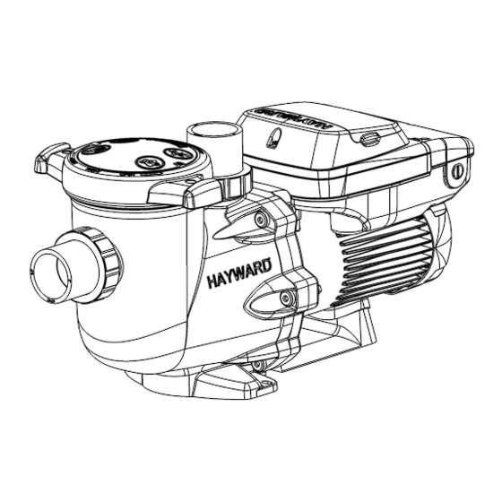
2.70 THP VS Pump Family
Owner's Manual
USE ONLY HAYWARD GENUINE REPLACEMENT PARTS
Contents
Safety Instructions.................1
Table of Contents...................5
Overview...............................6
Installation............................7
Operation.............................15
Maintenance........................22
Replacement Parts...............24
Troubleshooting...................25
HCP2500VSP
HL32950VSP
SPX3206Z1VSPE
SP3206VSPBH
SP32950VSP
W3SP3206VSP
Hayward Industries
1415 Vantage Park Dr., Suite 400
Charlotte, NC 28203
Phone (908)-355-7995
www.hayward.com
1011786 RevA
Advertisement
Table of Contents

Related Manuals for Hayward HCP2500VSP


Summary of Contents for Hayward HCP2500VSP
-
Page 1: Table Of Contents
Owner’s Manual Contents Safety Instructions....1 Table of Contents....5 Overview.......6 Installation......7 Operation......15 Maintenance......22 Replacement Parts....24 Troubleshooting....25 HCP2500VSP HL32950VSP SPX3206Z1VSPE SP3206VSPBH SP32950VSP W3SP3206VSP Hayward Industries 1415 Vantage Park Dr., Suite 400 Charlotte, NC 28203 Phone (908)-355-7995 www.hayward.com USE ONLY HAYWARD GENUINE REPLACEMENT PARTS... -
Page 2: Safety Instructions
All electrical wiring MUST be in conformance with all applicable local codes, regulations, and the National Electric Code (NEC). USE OF NON-HAYWARD REPLACEMENT PARTS VOIDS WARRANTY. ATTENTION INSTALLER - THIS MANUAL CONTAINS IMPORTANT INFORMATION ABOUT THE INSTALLATION, OPERATION, AND SAFE USE OF THIS VARIABLE SPEED PUMP THAT MUST BE FURNISHED TO THE END USER OF THIS PRODUCT. - Page 3 Mechanical Entrapment - There is potential for jewelry, swimsuits, hair decorations, fingers, toes, or knuckles to be caught in an opening of a suction outlet cover resulting in mechanical entrapment. USE ONLY HAYWARD GENUINE REPLACEMENT PARTS...
- Page 4 It is also necessary to allow the motor to cool for at least 20 minutes prior to maintenance to minimize the risk for burns. WARNING – Failure to install according to defined instructions may result in severe personal injury or death. SAVE THESE INSTRUCTIONS USE ONLY HAYWARD GENUINE REPLACEMENT PARTS...
- Page 5 Hayward Industries 1415 Vantage Park Drive, Suite 400, Charlotte, NC 28203 Technical Service Phone: (908) 355-7995 Manufacture Location: Hayward Industries, One Hayward Industrial Drive, Clemmons, NC 27012 Date Manufactured: The serial number is a 17 digit number Example serial number: 21122305456789001 The 5th - 8th digits are the “year &...
-
Page 6: Table Of Contents
User Interface Summary........................16 Menu Outline............................16 Initial Startup............................17 Configuration Menu..........................17 Timers Menu............................19 Preset Speed Setup Menu........................20 Diagnostic Menu..........................21 Stop/Resume............................21 Quick Clean............................21 Remote Stop............................22 Maintenance............................22 Storage/Winterization..........................22 Shaft Seal Change Instructions......................23 Replacement Parts..........................24 Troubleshooting............................25 General Problems..........................25 Check System Messages........................27 USE ONLY HAYWARD GENUINE REPLACEMENT PARTS... -
Page 7: Overview
This pump is easily installed either as a programmable stand-alone pump or with a Hayward or third party controller and features an easy-to-use digital control interface that can be mounted in four different positions on the pump or removed and mounted on the wall for total user convenience. -
Page 8: Installation
NOTE: It is recommended that a minimum length of straight piping (shown as “L” in above diagram), equivalent to 5 pipe size diameters, be used between the pump suction inlet and any plumbing fittings (elbows, valves, etc.). USE ONLY HAYWARD GENUINE REPLACEMENT PARTS... -
Page 9: Plumbing
If the time clock is used in this manner, it should be set to power the equipment during a time cycle when the VS pump is operating at an appropriate flow rate to operate the other equipment, as defined by the timers set in the Timer Menu. USE ONLY HAYWARD GENUINE REPLACEMENT PARTS... -
Page 10: Digital Control Interface Orientation
See page 13 for more information regarding connecting this pump and third party/non-software compatible Hayward controls. They can communicate with and be controlled by Hayward pool and spa controls. See page 14 for more information regarding connecting this pump and Hayward pool and spa controls. -
Page 11: Interface Wall Mounting
11. Apply power to the system and resume normal operation. The following diagrams illustrate the interface wall mounting procedure. Figure A Figure B Remove the Digital Control Interface for Wall Mounting Attach the blank cover onto the pump. Figure C USE ONLY HAYWARD GENUINE REPLACEMENT PARTS... -
Page 12: Installation Procedure
See Input Power Wiring section below for diagram. If the pump will be controlled using a Hayward pool control, connect the provided three-conductor cable as shown in the Hayward Automation Control Wir- ing diagram. See Hayward Automation Control Wiring section below. - Page 13 When communicating with the Omni family of controls, the HUA (Hayward Unique Address) is used for communication. For all other Hayward controls, the pump address must be set using the DIP switches on the drive PCB. To determine which address should be used, consult the appropriate Hayward pool control instal- lation manual, or visit our website at www.haywardpool.com.
-
Page 14: External Relay Speed Control Wiring
DIP switch #1 must be “ON”. This pump can be controlled from third party pool controls as well as Hayward controls that are not software compatible using relay contacts to select the speeds set in the Timer Menu (see page 19). -
Page 15: Wall Mounted Digital Control Interface Wiring
, so care must be taken when connecting to these terminals to ensure proper operation of user interface. If the “+12V” and “COM” terminals are used, DIP switch #1 must be “ON”. USE ONLY HAYWARD GENUINE REPLACEMENT PARTS... -
Page 16: Operation
Have a professional perform this test. Ensure all Hayward pump and system components are removed from system prior to performing test. WARNING – If circulation equipment must remain in the plumbing system during water pressure test, do not apply more than 10 psi pressure to the system. -
Page 17: User Interface Summary
Rename Timer “X” (where “X” equals 1 through 8) Pump Speed for Timer “X” (where “X” equals 1 through 8) Start/Stop Time for Timer “X” (where “X” equals 1 through 8) Choose Days for Timer “X” (where “X” equals 1 through 8) USE ONLY HAYWARD GENUINE REPLACEMENT PARTS... -
Page 18: Initial Startup
< > Use > if clock is correct. + change or > skip Set Day and Time Adjust day/time setting. < > Thursday 1:27p Move to next selection, then move to next menu item. USE ONLY HAYWARD GENUINE REPLACEMENT PARTS... - Page 19 NOTE: This sets the amount of time from the last button activation after the system has been unlocked to the point where the system becomes locked again. System Password Use to set password timeout. < > + change or > skip Move to next menu item. USE ONLY HAYWARD GENUINE REPLACEMENT PARTS...
-
Page 20: Timers Menu
Speed 4 buttons at the same time while powering on the drive, or by resetting all parameters in the Configuration Menu. If a mistake is made when entering the password, pressing Stop/Resume will cancel the action. If the pump is being controlled by a Hayward or third party pool control, the pump display can be locked by the password, however, the pump will respond to any and all commands being sent from the pool control. -
Page 21: Preset Speed Setup Menu
NOTE: Preset Speed settings can also be quickly updated without entering the Speeds Menu using the + and - arrow buttons to change the speed and then pressing the > button to save the new speed setting. USE ONLY HAYWARD GENUINE REPLACEMENT PARTS... -
Page 22: Diagnostic Menu
NOTE: When Stop/Resume is pressed at any time during normal operation, the above message will be displayed. The pump will stop within several seconds, and will remain stopped until Stop/Resume is pressed a second time, at which point the pump will resume normal operation. Quick Clean Screen SVRS inactive in Quick Clean mode USE ONLY HAYWARD GENUINE REPLACEMENT PARTS... -
Page 23: Maintenance
Keep motor clean. Keep motor air vents free of obstructions to avoid damage. Do NOT use water to hose off motor. • Occasionally, shaft seals must be replaced, due to wear or damage. Replace with genuine Hayward seal assembly kit. See “Shaft Seal Change Instructions” on the following page. -
Page 24: Shaft Seal Change Instructions
Disconnect all electrical power service to pump before beginning shaft seal replacement. • Only qualified personnel should attempt rotary seal replacement. Contact your local authorized Hayward Dealer or service center if you have any questions. • Refer to page 24 for pump component locations. -
Page 25: Replacement Parts
14. Fasten assembly to pump/strainer housing (item #3) using the six (6) 5/16” x 2” bolts (item #17). (Be sure housing gasket (item #14) is in place, and lubricated. Replace if damaged). Tighten bolts alternately and evenly to 185 inch-pounds according to housing bolt torque pattern detail. Replacement Parts USE ONLY HAYWARD GENUINE REPLACEMENT PARTS... -
Page 26: Troubleshooting
Comm Cable Kit * WhisperFlo is a registered trademark of Pentair Aquatic Systems, which is used herein for identification purposes only. This is a retrofit base for existing WhisperFlo pump installations. Pentair Aquatic Systems is not affiliated with Hayward Pool Products. Troubleshooting... - Page 27 Make sure the terminal board connections agree with the wiring diagram on the pump data plate label. Check for and correct any improper or loose wiring connections. Install noise filter (from home automation/power line communication equipment vendor) to prevent equipment interference. USE ONLY HAYWARD GENUINE REPLACEMENT PARTS...
-
Page 28: Check System Messages
Under certain circumstances, the “Drive overload” error can only be reset by cycling power applied to the pump. If the troubleshooting steps listed above do not help to resolve the error condition, then the problem may be internal to the motor/drive. Contact Hayward Technical Service at (908) 355-7995 for additional assistance. - Page 29 Move the equipment away from the receiver. Plug the equipment into an outlet on a circuit different from that to which the receiver is connected. Consult the dealer or an experienced radio/television technician for additional suggestions. USE ONLY HAYWARD GENUINE REPLACEMENT PARTS...
- Page 30 THIS PAGE IS INTENTIONALLY LEFT BLANK USE ONLY HAYWARD GENUINE REPLACEMENT PARTS...
- Page 31 THIS PAGE IS INTENTIONALLY LEFT BLANK USE ONLY HAYWARD GENUINE REPLACEMENT PARTS...
- Page 32 Hayward Industries, Inc. © 2024 Hayward Industries, Inc. All other trademarks not owned by Hayward are the property of their respective owners. Hayward is not in any way affiliated with or endorsed by those third parties. For patent information, refer to www.hayward.com/patents.
Need help?
Do you have a question about the HCP2500VSP and is the answer not in the manual?
Questions and answers