Table of Contents
Advertisement
Quick Links
Advertisement
Table of Contents

Related Manuals for Enovate Medical e997


Summary of Contents for Enovate Medical e997
- Page 1 Articulating Wall Arm MANUAL | IM002-Rev004 10.25.23...
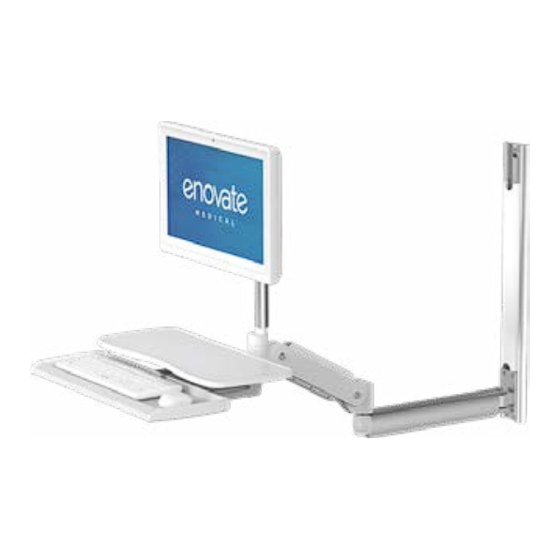
- Page 2 The Enovate Medical e997 Wallstation was designed to set a new standard in qual- ity. Enovate Medical’s goal is to provide a wallstation that is ready for years of use, and backed by a commitment of exemplary service and support.
-
Page 3: Table Of Contents
• e997 MANUAL Warnings • e997 MANUAL WARNINGS CONTENTS WARNINGS ............................3 Important Warnings Electrical Shock Warning SERVICE AND REPLACEMENT ....................... 4 HARDWARE & COMPONENTS ......................5 OPTIONAL COMPONENTS ......................6 The symbols below represent safety warnings that require significant HARDWARE INCLUDED ........................ -
Page 4: Warnings
HARDWARE & COMPONENTS SERVICE AND REPLACEMENT Warranty will be void if an attempt to service or replace any part of the Enovate Medical Wall Arm is made unless directed to do so through Enovate Medical approved documentation (i.e., this User Manual or other instructions). Only Enovate Medical or an Enovate-certified entity may service or replace the Enovate Medical Wall Arm components. -
Page 5: Optional Components
Hardware & Components • e997 MANUAL Hardware & Components • e997 MANUAL OPTIONAL COMPONENTS HARDWARE INCLUDED 6-8x* 6-8x* 1/4" 20 x 2 1/2" SNAPTOGGLE® Anchor (Pre-installed on the Cross Drive Metal Screw Part WS0900200 riser arm) Large Slotted (for use with SNAPTOGGLE... -
Page 6: Tools Required
TOOLS REQUIRED IMPORTANT BEFORE YOU BEGIN INSTALLATION: Enovate Medical does not recommend installation of its wall mounted product to drywall only. This product should be mounted to metal or wood studs or on ¾” plywood backing board securely mounted to studs. Do not mount to floating studs. -
Page 7: Mounting
1/2" Button Head Screws using a 1/8" Allen Wrench. NOTE: Always mount the e997 to a wall stud or 3/4" plywood backing board that is securely mounted to studs. Do not mount to floating studs. 1. Align the holes on the wall track end cap with the corresponding holes on the wall track. -
Page 8: Toggle Mounting
1/2” ASSEMBLY • e997 MANUAL ASSEMBLY • e997 MANUAL TOGGLE MOUNTING - TOGGLE MOUNTING CONTINUED (PREFERRED MOUNTING METHOD) Must be 1-7/8” minimum clearance behind wall for STEP 1 STEP 5 - Continued channel rotation. Install the wall track end cap to the wall track using two 10-24 x 1/2" Button Hold the SNAP-TOGGLE®... -
Page 9: Metal Stud Mounting
STEP 3 STEP 3 Locate the exact center line of the wall studs where the e997 wallstation Align the wall track matching the toggles installed on page 12. Secure the will be mounted along with the bottom of the track height from the floor. -
Page 10: Carriage Arm Mounting
Assembly • e997 MANUAL Assembly • e997 MANUAL CARRIAGE MOUNTING CARRIAGE ARM MOUNTING (EXTENSION ARM) (NON-EXTENSION ARM) STEP 1 STEP 1 Wall Track Cover Level the wall track. Tighten all toggle Level wall track and remove the wall Wall Track... -
Page 11: Riser Arm, Monitor Pole, Edesk And Simple Keyboard Tray Assembly
Assembly • e997 MANUAL Assembly • e997 MANUAL RISER ARM, MONITOR POLE, EDESK AND SIMPLE STEP 3 Lay the eDesk or simple keyboard on a flat surface. Ensure the pivot KEYBOARD TRAY ASSEMBLY mount is facing you and pointing upward. - Page 12 Assembly • e997 MANUAL Assembly • e997 MANUAL STEP 5 Slide the shim washer (P0001840) onto the end of the monitor pole. Begin STEP 4 hand threading the 3/4-10 Nut (P0001839) turning it slowly to ensure proper INSTALLATION WITHOUT EXTENSION ARM alignment and avoid cross threading.
-
Page 13: Mounting The Monitor
Dual Lock Pads This gap ensures that the wall arm Attach the keyboard to the tray (P0000050) can fully retract when the e997 is not using the four dual-lock pads. in use. First, peel off the protective backing from each pad and adhere them to the keyboard's corners. -
Page 14: Standard Keyboard Cable Management
Cable Management • e997 MANUAL Cable Management • e997 MANUAL STANDARD KEYBOARD CABLE MANAGEMENT EDESK CABLE MANAGEMENT STEP 1 STEP 1 With the keyboard tray fully extended, run the keyboard and mouse cables Fully extend keyboard tray. through the cut out located on the back of the keyboard tray. Tightly secure the cables with a zip-tie to the cable tie adhesive pad previously installed. - Page 15 Cable Management • e997 MANUAL Cable Management • e997 MANUAL STEP 5 STEP 6 NOTE - Optional eDesk: It is important to pull the keyboard tray to the fully Replace the keyboard tray and place the mouse and keyboard into place.
-
Page 16: Riser Arm Cable Management
Shepherd hook or large loop to allow adequate cables on the riser arm with the cable loom (part P0000119) cable when the e997 is retracted. Snap the cable cover back into place. Plug all the cables (power, video, USB extensions) into the appropriate ports on NOTE: create a shepherd’s hook at the pivot point by allowing enough slack to ensure the eDesk... -
Page 17: Routing Cables Through The Wall Track
ROUTING CABLES THROUGH THE WALL TRACK ROUTING CABLES THROUGH EXTENSION ARM NOTE: Determine the direction the e997 will close. If it closes to the left of the STEP 1 wall track, route the cables to the right, and vice versa. -
Page 18: Install The End Cap Or Cpu Bracket
Cable Management • e997 MANUAL Cable Management • e997 MANUAL INSTALL THE END CAP OR CPU BRACKET - INSTALL THE END CAP OR CPU BRACKET CONT. STEP 5 STEP 4 CPU Bracket Position the CPU inside the bracket. Secure the end cap with 10-24 x 1/2"... -
Page 19: Riser Arm Tension Adjustment
Adjustments • e997 MANUAL Adjustments • e997 MANUAL WORK SURFACE AND MONITOR LEVELING RISER ARM TENSION ADJUSTMENT STEP 1 Ensure riser arm is parallel to the floor. LEVEL Movement when folded STEP 1 STEP 2 With arm folded as close to the wall as possible lower riser arm to access Using 5/16 Allen wrench tighten or loosen the screw clockwise or counter- set screws. -
Page 20: Keyboard Tilt
Adjustments • e997 MANUAL Accessories • e997 MANUAL KEYBOARD TILT MOUNTING MOUSE HOLDER (STANDARD SIMPLE KEYBOARD TRAY) STEP 1 STEP 1 Peel backing from two-sided tape Fold eDesk to stored position. on back of mouse holder. STEP 2 Remove plastic cover plate. -
Page 21: Arm Extension
Movement • e997 MANUAL Movement • MANUAL Movement • e997 MANUAL RANGE OF MOVEMENT ARM EXTENSION (WITH EXTENSION ARM) Both arms extended: One arm extended No extension 57” from the wall 31” from the wall 16 3/8” from the wall... -
Page 22: Range Of Movement
Movement • e997 MANUAL Parts List • e997 MANUAL PARTS LIST RANGE OF MOVEMENT (NO EXTENSION ARM) PARTS ORDERING: Contact Enovate Medical Technical Services department at (615)- 896- 1652 x303 or (888)-909-8930 x303 Adhesive Mouse Pad AM0100050 Cable Loom P0000119... - Page 23 INDEX • e997 MANUAL Index ACCESSORIES 37 ADHESIVE MOUSE PAD 5, 41 ADJUSTMENTS 32 ARM ASSEMBLY 17 BUTTON HEAD SCREW 41 CABINET ASSEMBLY 14 CABINET CABLE MANAGEMENT 25 CABLE LOOM 24 CABLE TIE & ADHESIVE PAD 24 CPU BRACKET 26, 27, 28, 29, 31, 41...
- Page 24 INDEX • e997 MANUAL...
Need help?
Do you have a question about the e997 and is the answer not in the manual?
Questions and answers