Table of Contents
Advertisement
Quick Links
Service Manual
Flow Logic (MINI) VVFA Series
R410A
English Manual
VVFA-125R-01M22
VVFA-150R-01M22
VVFA-150R-01T32
IMPORTANT NOTE:
Read this manual carefully before installing or operating your new air conditioning unit. Make sure to
save this manual for future reference.
22.AW.VVFA.125-150.R410A.SM.EN.05.03.Rev01
Advertisement
Table of Contents

Related Manuals for Airwell VVFA Series


Summary of Contents for Airwell VVFA Series
- Page 1 Service Manual Flow Logic (MINI) VVFA Series R410A English Manual VVFA-125R-01M22 VVFA-150R-01M22 VVFA-150R-01T32 IMPORTANT NOTE: Read this manual carefully before installing or operating your new air conditioning unit. Make sure to save this manual for future reference. 22.AW.VVFA.125-150.R410A.SM.EN.05.03.Rev01...
-
Page 2: Table Of Contents
CONTENTS 1. General Information.....................1 1.1 Outdoor models and external appearance .............1 1.2 Indoor units.....................2 1.3 Feature ......................4 2. Specification ......................5 3. Dimension......................7 4. Piping Diagram ....................11 5. Wiring Diagram....................10 6. Capacity Calculation Due to Capacity Modification Coefficient ......12 7. Operation range....................14 8. -
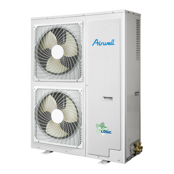
Page 3: General Information
1. General Information 1.1 Outdoor models and external appearance VVFA-125R-01M22 VVFA-150R-01M22 VVFA-150R-01T32... -
Page 4: Indoor Units
1.2 Indoor units ROUND-WAY SMART AIR FLOW 4-WAY CASSETTE TYPE/PB-700lB CASSETTE/ Panel for CVTA CVQA-025/022/015N-01M22 CVQA-050/045/035N-01M22 CVTA-025/022N-01M22 CVTA-035N-01M22 4-WAY CASSETTE TYPE/CCV PANEL 90X90 CVTA-050/045N-01M22 AWSI-CCV018-N11 CVTA-070N-01M22 AWSI-CCV024-N11 CVTA-110/090N-01M22 AWSI-CCV030-N11 AWSI-CCV038-N11 CVTA-160/140N-01M22 AWSI-CCV048-N11 2-WAY CASSETTE TYPE/ P1B-1055IB ONE WAY CASSETTE TYPE/Panel for CVPAto s12 CVOA-025N-01M22 CVPA-035N-01M22 CVOA-035N-01M22... - Page 5 N HIGH WALL MED ESP DUCT TYPE (50/100Pa) DVMA-015N-01M22 DVMA-022N-01M22 HVVA-025/022N-01M22 DVMA-025N-01M22 HVVA-035N-01M22 DVMA-035N-01M22 HVVA-050/045N-01M22 HVVA-070N-01M22 DVMA-045N-01M22 DVMA-050N-01M22 DVMA-080/070N-01M22 HVVA-090N-01M22 CONSOLE XVVA-050/035/025N-01M22 AWSI-HRV0800-N11 AWSI-HRV1000-N11 Note: The indoor unit connected to Flow Logic IV must be the new indoor manufactured after January 1, 2019 (the PCB is upgraded program)
-
Page 6: Feature
1.3 Feature New platform, new outlook Spiral air outlet grille Better outlook and lower noise Built-in charge valve Safer and easier maintenance Round corner Better outlook & safer High energy efficiency DC inverter compressor Haier takes DC INV. compressor, 5% power input lower. (14kw) DC fan motor and 550mm big fan 38% power input lower and 8% airflow higher Larger heat exchanger... -
Page 7: Specification
Model VVFA-150R-01T32 VVFA-150R-01M22 VVFA-125R-01M22 1/220~240/50/60 Power supply Ph/V/Hz 3/380~415/50/60 1/220~240/50/60 Rated capacity 12.60 15.50 15.50 Rated capacity kBtu/h 43.0 52.9 52.9 Rated power input 3.11 4.31 4.31 Cooling Max. power input 4.05 3.60 3.60 Rated current 14.7 20.4 Max. current 34.1 36.9 12.3... - Page 8 Model VVFA-125R-01M22 VVFA-150R-01T32 VVFA-150R-01M22 Power supply Ph/V/Hz 1/220~240/50/60 3/380~415/50/60 1/220~240/50/60 Number of rows Tube pitch(a)x row 21*18.186 21*18.186 21*18.186 pitch(b) Fin spacing 1.40 1.40 1.40 Fin type (code) Corrugated Fin Coating Type optional Hydrophilic aluminum Hydrophilic aluminum Hydrophilic aluminum Outdoor coil Salt Spray Test Hour Duration...
-
Page 9: Dimension
3. Dimension 1340 406 450... -
Page 10: Piping Diagram
4. Piping Diagram... - Page 11 Part name Sign Function Date Note Capacity control, meet indoor load request by adjusting frequency and Compressor 20°C opening and closing fixing frequency compressor. Pressure switch High pressure protection 4.15Mpa, OFF Electronic In heating, refrigerant flow control Φ3.0 expansion valve (subcooling valve) 1.
-
Page 12: Wiring Diagram
5. Wiring Diagram YEVFD125-H15 VVFA-125R-01M22 VVFA-150R-01M22 0150518287 <WIRING DIAGRAM> TD TE(1) TS TA CN13 CN12 AC-L AC-N 6.3A 250VAC FUSE1 CN2 CN3 CN4 CN5 CN6 CN7 CN29 CN28 CN30 CN19 CN21 INV BOARD CN26 CN18 LED4 LED2 CN17 Tfin COMP CONTROL BOARD CN20 CN16... - Page 13 VVFA-150R-01T32 0150520925 <WIRING DIAGRAM> TD TE(1) TS TA PS PD 6.3A 250VAC FUSE1 CN1 CN2 CN3 CN29 CN28 CN30 CN19 CN21 CN26 CN32 CN18 LED4 LED2 CN31 DISPLAY CN17 CN30 CN20 CN16 HEATER CONTROL BOARD CN25 SW01 SW02 ACFAN2 Tfin CN15 CN24 ACFAN1...
-
Page 14: Capacity Calculation Due To Capacity Modification Coefficient
6. Capacity Calculation Due to Capacity Modification Coefficient (1) Calculation method of refrigerating capacity----cooling capacity to be known=refrigerating capacity*(A*B*C*D*E)W A. Capacity compensation value of indoor B. Capacity compensation value of outdoor air wet-bulb temperature condition air dry-bulb temperature condition 40 43 Indoor air wet-bulb temperature (°C ) Outdoor air dry-bulb temperature (°C ) C. - Page 15 (2) Calculation method of refrigerating capacity----heating capacity to be known=refrigerating capacity*(A*B*C*D*E*F)W A. Capacity compensation value of indoor B. Capacity compensation value of outdoor air air dry-bulb temperature condition wet-bulb temperature condition Indoor air dry-bulb temperature (°C) Outdoor air wet-bulb temperature (°C) C.
-
Page 16: Operation Range
7. Operation range Cooling Heating Indoor temperature(℃DB) Indoor temperature(℃DB)... -
Page 17: Sound Level
8. Sound Level (1) Testing illustration 1.18m 1.18m 2) Testing condition: a. Unit running in the nominal condition b. Test in the semi-anechoic chamber c. Noise level varies from the actual factors such as room structure, etc. VVFA-125R-01M22 NC-60 NC-50 NC-40 NC-30 NC-20... -
Page 18: Outdoor Piping Installation
9. Outdoor Piping Installation 9.1 Product features • The outdoor uint adopts "simultaneous control" type, all indoors should be heating or cooli.ng simultaneously. • To protect compressor,before startup,the unit should be electrified for 12 hours.If the unit is not used for a long time, please cut off the power to save energy, or the unit will consume the power. - Page 19 • The maintenance cover plate of the indoor or outdoor machine is forbidden when the main circuit power supply is not cut off. • The leakage of refrigerant can cause the air to be thin and difficult to breathe. In case of refrigerant leakage, close the main valve, extinguish any flame and contact the local distributor immediately.
-
Page 20: Transportation And Lifting
Arrival inspection • After receiving the machine, should check whether there is transport damage. If any damage is found on the surface or inside, it shall be reported immediately to the shipping company in writing. • Check the product model, electrical parameters (power supply, voltage, frequency) and accessories to determine whether they meet the requirements. -
Page 21: Installation Instruction
9.4 Installation instruction In installation, please check specially the below items: • If the connected units quantity and the total capacity is in the allowable range? • If the refrigerant pipe length is in the limited range? • If the pipe size is proper? And if the pipe is installed horizontally? •... - Page 22 Note: 1. In snowy area, install the unit under the bracket or the snow-proof cover against the accumulative snow on the unit. 2. Do not install the unit at the place where the flammable gas will leak. 3. Install the unit at the strong enough place. 4.
- Page 23 (3) Multi-unit installation in front and back (unit: in.(mm)) The top and two side surfaces must be exposed to open space, and barriers on at least one side of the front and back shall be lower than the outdoor unit. •...
- Page 24 If the coating on the fastening area is stripped off, the nuts rust easily. Dimensions (bottom view) (unit of measurement: mm) A 600 A leg pitch1 B leg pitch2 C Front grill (air outlet side) D Drain hole E Bottom frame F Knock-out hole (for piping line) (5) Refrigerant pipe connection...
- Page 25 Pipe specification: 1. Pipe "a" diameter (between indoor and branch pipe) (depends on indoor pipe) Please refer to the indoor air conditioner manual. 2. Pipe "b" diameter (between branch pipes) Total indoor capacity after the branch pipe Gas pipe (mm) Liquid pipe (mm) (x100W) X<112 Ø15.88...
- Page 26 Long pipe and high drop 1. Allowable pipe length and height difference Outdoor unit First branch piping Indoor unit Permissible value Piping part Total length of piping (actual length) 300m L1+L2+L3+L4+a+b+c+d+e Single way max. pipe length Actual length 150m L1+L2+L3+L4+e Pipe length between outdoor and first branch pipe 110m Piping...
- Page 27 Note: 1. When connecting the pipe and the outdoor, please pay attention to the outdoor pipe dimension. 2. When adjusting the diameter among pipes and among the units, please must execute at the branch pipe side. 3. When welding with hard solder, please must blow nitrogen. If not, a number of oxide will be produced and cause heavy damage.Besides,to prevent water and dust into the pipe, please make the brim as outer roll.
- Page 28 • The outdoor gas pipe and the refrigerant distributing pipe, as well the refrigerant distributing pipe and the branch pipe should be welded with hard solder. • Weld the pipe at the same time charge the nitrogen. Or it will cause a number of impurity (a film of oxidation) to clog the capillary and the Seal the pipe end with expansion valve, further cause the deadly failure.
- Page 29 Because the unit is with refrigerant R410A, the below issues should be paid attention: • To prevent the different oil into the pipe, please use the special tool for R410A, especially for gauge manifold and charging hose. • To prevent the compressor oil into the refrigerant cycle, please use the anti-counter-flow adapter. (8) Check vale operation Open/close method: •...
-
Page 30: Outdoor Wiring Installation
10. Outdoor Wiring Installation Inspect • To ensure that the electrical equipment used on the installation WARNING site (main power switch, circuit breaker, wire, conduit and • Switch off the main power switch of the wiring terminals, etc.) have been selected according to current indoor and outdoor machine for more than data, to ensure that the device in line with national standards. - Page 31 Communication wiring figure Indoor 1 (AC fan motor) Indoor 2(DC fan motor) Indoor 3 Indoor 4 Indoor 5 Indoor 6 The master outdoor and all indoor units are in parallel through 2 non-polar wires. There are three connecting ways between wired control and indoor units: A.
- Page 32 Type Series PCB Code 4-way Cassette 0151800113 0151800161B 2-way Cassette 0151800113 Convertible 0151800161C Slim Low ESP Duct 0151800113 Low ESP Duct 0151800113 AC fan motor 0151800113 Medium ESP Duct 0151800113 0151800161C 0151800113 High ESP Duct 0151800113 Fresh Air 0151800113 Built-In Floor Standing 0151800227 Round Flow 4-Way Cassette 0151800244BA...
- Page 33 Outdoor power source and power cable Item Ground wire Rated current of residual Power cable Circuit Power circuit breaker (A) section breaker Section source Ground fault interruptor (mA) Screw response time (S) Model 50A 30mA below 0.1S VVFA-125R-01M22 1PH, 220-240V~, 50/60Hz 50A 30mA below 0.1S VVFA-150R-01M22 20A 30mA below 0.1S...
- Page 34 Item Rated current of residual Communication wire section Rated current Power cable circuit breaker(A) Wire length of overcurrent Indoor section Ground fault Outdoor/indoor Indoor/indoor breaker total interruptor(mA) current (A) response time(S) <10 20A, 30mA, below 0.1s ≥10 and <15 30A, 30mA, below 0.1s 2-core ×...
-
Page 35: Outdoor Unit Pcb
11. Outdoor Unit PCB 0151800146J LED1 LED3 LED2 LED4... -
Page 36: Dip Switch Setting
12. Dip Switch Setting (1) BM1 introduction Definition Introduction Begin to search indoor Indoor searching after BM1_1 startup Stop searching indoor and lock the quantity Celsius area Celsius / Fahrenheit area BM1_2 selection Fahrenheit area 30Pa BM1_3 Static pressure selection 0Pa (default) Energy saving priority Priority selection for energy... - Page 37 Definition Introduction Heat pump (default) Cooling only or heat pump BM2-1 selection Cooling only BM2_2 BM2_3 Outdoor model selection BM2_4 Single phase BM2-5 Power supply selection 3-phase New communication protocol (default) BM2-6 Communication protocol selection Old communication protocol BM2-7 BM2-8 Start mode selection First on indoor unit priority Last on indoor unit priority...
-
Page 38: Monitor Tools
13. Monitor Tools Main function instruction: By setting the rotary switch, the digital tube will display the outdoor and indoor unit parameters (the outdoor current, discharge temp., suction temp., defrosting temp., coil temp. and outdoor ambient temp.; indoor unit coil temp. and valve open angle and so on), the data is inform of decimal integer. - Page 39 SW01 SW02 Digital tube display Td discharging temperature (unit: ℃) Ta outdoor ambient temperature (unit: ℃) Ts suction temperature (unit: ℃) Te defrosting temperature (unit: ℃) Toil oil temperature (unit: ℃) Pd high pressure (unit: kg, one decimal) Ps low pressure (unit: kg, one decimal) Outdoor PMV valve open angle (unit: pls, max.
-
Page 40: Outdoor Unit Control
14. Outdoor Unit Control 1. Compressor startup control After receiving the outdoor startup instruction, outdoor open SV1 30 seconds and then standby. When startup, the compressor will keep for 3 min at 45rps (when Ta<40°C) or 3 min at 40rps (when Ta>=40°C). In cooling mode, meet running 1min &... - Page 41 Pd(MPa) 《A area》Pd<1.0 MPa, drop step by step at the lowest fan speed (fan speed No.1 ) running 1 min , OFF 《B area》1.0MPa≤Pd<1.5 MPa Reduce the speed per 1 class /20s until to the lowest 《C area》1.5MPa≤Pd<2.2 MPa Keep the current fan speed 《D area》2.2MPa≤Pd<3.2MPa Increase the speed per 1 class/20s 《E area》Pd≥3.2 MPa...
- Page 42 4. Defrosting control In order to have the effect heating operation, need defrosting control. 4.1 Entering condition: Ta≤20°C • & After heating startup 60min • OR Last defrosting~ heating cumulative operation time is more than 60 minutes A: Ta≥6°C, Te≤-10°C For 5min continuously •...
- Page 43 B: In heating mode When load rate<25%: after 1 hours, 4-way valve doesn't reversing oil return operation 25%≤load rate<50%: after 2 hours, 4-way valve The master unit compressor cumulative • OR • & doesn't reversing oil return operation operation time Load rate≤30% 50%≤load rate<75%: after 4 hours, 4-way valve •...
-
Page 44: Failure Code
15. Failure code Digital tube Indication indication on wired Failure code Failure description Remarks on master controller definition unit (hex) Defrosting temp. Resumable sensor Te failure Ambient temp. Resumable sensor Ta failure Open circuit or short circuit for continuous 60seconds, alarm Suction temp. - Page 45 Digital tube Indication indication on wired Failure code Failure description Remarks on master controller definition unit (hex) Communication with No communication for 30 seconds continuously, when Resumable inverter board failure communication is normal, resume Compressor frequency continuous operation after 1 minute, CT current is too low Once compressor frequency ≥70Hz, current sensor for five minutes...
- Page 46 Digital tube Indication indication on wired Failure code Failure description Remarks on master controller definition unit (hex) Upper DC motor 71-0 Running at speed below 20rpm for 40s, or running lower than failure 70% of target speed for 2 minutes, 3 minutes after recovery, If it Lower DC motor occurs 3 times in an hour, confirm the failure 71-1...
- Page 47 Digital tube Indication indication on wired Failure code Failure description Remarks on master controller definition unit (hex) Module over current Module over current (software) (software) Compressor startup Compressor continuously startup 5 times all failed. 3 times in an failure hour, confirm Detecting circuit of Current detection sensor of inverter controller is abnormal or failure;...
-
Page 48: Troubleshooting
16. Troubleshooting [20-23] Temperature sensor failure If sensor terminal is fixed well Reconnect If sensor resistor Replace sensor /characteristic is proper Check if PCB is faulty, if yes, replace it [122] Radiator temp. sensor of transducer abnormal Check if connection between temp. Adjust connection sensor and inverter board Measure if temp. - Page 49 [26-0, 26-1, 26-2] Communication circuit between indoor and outdoor If wiring between P and Q Modify the communication wire is wrong or broken down If wire of on outdoor Modify the port connecting board is normal If the wire on indoor PCB is normal If indoor and outdoor are Connect power source...
- Page 50 [28, 29] High/low pressure sensor failure If sensor terminal is fixed well Reconnect If voltage between red terminal and black terminal is 5V when Replace PCB testing pressure sensor by multimeter If voltage between white terminal and black Replace pressure sensor terminal is 0.5V~3.5V when testing pressure sensor by multimeter Replace connecting board...
- Page 51 [30] High pressure switch failure If connection between pressure Re-connect switch and connecting board is good If the system pressure meets the Replace pressure switch condition that pressure switch shuts off Make pressure switch close, measure if terminal is conductive by multimeter If the system is clogged Check the piping system Make pressure switch terminal...
- Page 52 [33] Outdoor EEPROM failure Reconnect If the EEPROM is fixed well Replace EEPROM [34] Protection of discharging temp. too high If sensor terminal is fixed Reconnect well If sensor resistor Replace sensor /characteristic is proper If the system is Charge refrigerant lack of refrigerant Replace connecting board...
- Page 53 [35] 4-way valve reversing failure If connection between 4-way valve Re-connect and connecting board is good If system meets condition Check if SV1 leaks of 4-way valve reversing: Pd-Ps>0.6MPa Measure if CN49 voltage on connecting board is Replace connecting board 220VAC after 4-way valve reversing condition is met If compressor running...
- Page 54 [39-0, 39-1] Low pressure too low and compression ratio too high If actual pressure is in conformance with the Replace pressure sensor measured data by sensor Check if stop valve Open stop valve is open fully Check if system is Recharge refrigerant lack of refrigerant Check if terminal of...
- Page 55 [40] High pressure too high failure If characteristic of high pressure Replace pressure sensor sensors are normal If stop valve Open stop valve opens fully If in cooling Check fan motor outdoor fan motor runs normally If in heating indoor fan Check indoor motor runs normally and if filter is clogged...
- Page 56 [43] Discharging temp. sensor Td too low protection If the sensor characteristic Replace the sensor is correct If the terminal of Reconnect sensor is fixed well In cooling mode, when the Replace of adjustment the indoor unit off if the EEV can't indoor unit EEV completely close Check if refrigerant...
- Page 57 [53] CT Current too low or current sensor failure Check if where between connecting board and CT Re-connect board is connected well (CN9) Replace wire Check if CT wire is conductive Check if it is normal after Replace connecting board replacing CT board CT board is broken down...
- Page 58 [64] CT current too high Check if wire between connecting board and module Re-connect is connected normally Check if CT wire is conductive Replace wire If normal after If temperature on top of fixed If AC contactor replacing CT frequency compressor is too work detector high...
- Page 59 [71-0,71-1 ] DC motor blocked Rotate fan motor by Replace fan motor hand to check if there is obviously fiction Check the motor and Re-connect PCB connection is well Forced the fan in low speed, measure if it has alternating Replace the motor voltage between FG and GND Replace the outdoor PCB...
- Page 60 [75-0, 75-4] Pressure difference between high pressure and low pressure is abnormal Check if high/ low pressure Re-connect sensor is connected well Check if compressor wire is Correct compressor wire connected normally If wire of inverter compressor Correct compressor wire are connected oppositely If 4-way valve is Replace 4-way valve...
- Page 61 [82] Compressor current protection [108] Transient over current in IPM module rectifier side software [110] IPM module hardware over current [123] Transient over current in IPM module rectifier side hardware Improver power supply circuit Check if voltage of power supply in normal Check if wire of electric box Correct the wiring due to diagram is correct and if compressor...
- Page 62 [111] Compressor out of control [118] the compressor start failure Check if voltage of power supply is normal Improve power supply circuit Check the wires among U, V, Replace the wires W of compressor are normal If compressor is normal (compressor coil resistor, insulation) Replace the compressor Compressor load too much,...
- Page 63 [113] Protection of overload Improve power supply circuit Check if voltage of power supply is normal Check if wire of electric box is correct Correct the wiring due to diagram If compressor is normal Replace compressor (compressor coil resistor, insulation) If power module is normal Replace power module Compress load too much,...
- Page 64 [115] Voltage too high of DC bus line of transducer Check if voltage of power Improve power supply circuit supply is normal Check if wire of electric box is correct Correct the wiring due to diagram Measure if DC bus line Circuit of DC bus line voltage on voltage between P and N of inverter control board abnormal,...
- Page 65 [117] Transducer over current (software protection) Check voltage of power supply is normal Improve power supply circuit Check if wire of electric box is correct Correct the wiring due to diagram If compressor is normal Replace compressor (compressor coil resistor, insulation) If power module is normal Replace power module Compressor load too much,...
- Page 66 [120] Power supply of transducer abnormal Improve power supply circuit Check if voltage of power supply is normal Check if wire of electric box is correct Correct the wiring due to diagram Adjust or replace relay If relay or AC contactor acts well or AC contactor Measure if DC bus line DC bus line voltage circuit on...
- Page 67 [122] Radiator temp. sensor of transducer abnormal Check if connection between Adjust connection temp. sensor and inverter board Replace sensor Measure if temp. sensor resistor is normal Replace inverter control board...
- Page 68 Appendix I: Sensor Resistance Table Code Resistance Description 0010450192 Outdoor ambient temp. sensor 0010450194 Defrosting temp. sensor 0010451303 Discharging temp. sensor 0010451307 Suction temp. sensor...
- Page 69 R80=50kΩ±3% B25/80=4450K±3% Temp Resistance (kΩ) % (Resist. Tol) (°C) Rmax R (t) Normal Rmin MAX (+) MIN (-) 1749.01 1921.99 2094.97 9.00 9.00 1651.43 1813.27 1975.10 8.93 8.93 1560.17 1711.65 1863.13 8.85 8.85 1474.74 1616.59 1758.45 8.78 8.78 1394.71 1527.61 1660.51 8.70 8.70...
- Page 70 R80=50kΩ±3% B25/80=4450K±3% Temp Resistance (kΩ) % (Resist. Tol) (°C) Rmax R (t) Normal Rmin MAX (+) MIN (-) 272.33 290.41 308.49 6.23 6.23 260.43 277.49 294.56 6.15 6.15 249.10 265.22 281.33 6.08 6.08 238.33 253.54 268.75 6.00 6.00 228.07 242.44 256.80 5.93 5.93...
- Page 71 R80=50kΩ±3% B25/80=4450K±3% Temp Resistance (kΩ) % (Resist. Tol) (°C) Rmax R (t) Normal Rmin MAX (+) MIN (-) 64.99 67.42 69.84 3.60 3.60 62.61 64.90 67.19 3.53 3.53 60.34 62.49 64.65 3.45 3.45 58.15 60.19 62.22 3.38 3.38 56.06 57.97 59.89 3.30 3.30...
- Page 72 R80=50kΩ±3% B25/80=4450K±3% Temp Resistance (kΩ) % (Resist. Tol) (°C) Rmax R (t) Normal Rmin MAX (+) MIN (-) 20.07 21.05 22.03 4.67 4.67 19.41 20.37 21.34 4.73 4.73 18.77 19.72 20.67 4.80 4.80 18.16 19.09 20.02 4.87 4.87 17.57 18.49 19.40 4.93 4.93...
- Page 73 R25=10kΩ±3% B25/50=3700K±3% Temp Resistance (kΩ) % (Resist. Tol) (°C) Rmax R (t) Normal Rmin MAX (+) MIN (-) 145.82 135.02 124.22 7.00 7.00 138.07 129.13 120.18 6.93 6.93 131.79 123.34 114.89 6.85 6.85 125.67 117.68 109.70 6.78 6.78 119.71 112.18 104.65 6.71 6.71...
- Page 74 R25=10kΩ±3% B25/50=3700K±3% Temp Resistance (kΩ) % (Resist. Tol) (°C) Rmax R (t) Normal Rmin MAX (+) MIN (-) 24.74 23.69 22.63 4.45 4.45 23.61 22.62 21.63 4.38 4.38 22.54 21.61 20.68 4.31 4.31 21.52 20.65 19.77 4.24 4.24 20.56 19.74 18.92 4.16 4.16...
- Page 75 R25=10kΩ±3% B25/50=3700K±3% Temp Resistance (kΩ) % (Resist. Tol) (°C) Rmax R (t) Normal Rmin MAX (+) MIN (-) 5.36 5.15 4.94 4.06 4.06 5.17 4.96 4.76 4.13 4.13 4.98 4.78 4.58 4.19 4.19 4.80 4.60 4.41 4.25 4.25 4.63 4.43 4.24 4.31 4.31...
- Page 76 R25=10kΩ±3% B25/50=3700K±3% Temp Resistance (kΩ) % (Resist. Tol) (°C) Rmax R (t) Normal Rmin MAX (+) MIN (-) 1.68 1.58 1.48 6.19 6.19 1.63 1.53 1.43 6.25 6.25 1.58 1.48 1.39 6.31 6.31 1.53 1.44 1.35 6.38 6.38 1.49 1.40 1.31 6.44 6.44...
- Page 77 Appendix II: Enthalpy-Humidity Chart 0 10 0mmHg Humidity d. g/kg dry air k∫ /kg kcal /kg Wet ait enthalpy-humidity chart 1000 1013.25mbar (10Pa) Atmosphetic ptessute 760mmHg =1.01t+0.001d(2500+1.84t)k∫/kg dtyait =1.24t+0.001d(597.3+0.44t)kcal/kg dtyait...
- Page 78 Consult with the sales agency or manufacturer for details. ATTENTION : Le design et les données techniques sont donnés à titre indicatif et peuvent être modifiés sans préavis. AIRWELL RESIDENTIAL SAS 10,Rue du Fort de Saint Cyr, 78180 Montigny le Bretonneux - France www.airwell.com...
Need help?
Do you have a question about the VVFA Series and is the answer not in the manual?
Questions and answers