Advertisement
Quick Links
EX600-TF223-093EN
ORIGINAL INSTRUCTIONS
Instruction Manual
Fieldbus device - SI unit for EtherNet/IP
IO-Link compatible
56-EX600-SEN7/8-X10
II 3G Ex ec IIC T4 Gc -10
C ≤ Ta ≤ 50
C
o
o
II 3D Ex tc IIIC T66
C Dc IP67
o
The intended use of this product is to control pneumatic valves and I/O
while connected to the EtherNet/IP
TM
protocol.
1 Safety Instructions
These safety instructions are intended to prevent hazardous situations
and/or equipment damage. These instructions indicate the level of
potential hazard with the labels of "Caution," "Warning" or "Danger."
They are all important notes for safety and must be followed in addition
to International Standards (ISO/IEC)
*1)
, and other safety regulations.
*1)
ISO 4414: Pneumatic fluid power — General rules and safety
requirements for systems and their components.
ISO 4413: Hydraulic fluid power — General rules and safety
requirements for systems and their components
IEC 60204-1: Safety of machinery - Electrical equipment of machines.
Part 1: General requirements
ISO 10218-1: Robots and robotic devices - Safety requirements for
industrial robots - Part 1: Robots
• Refer to product catalogue, Operation Manual and Handling
Precautions for SMC Products for additional information.
• Keep this manual in a safe place for future reference.
Danger indicates a hazard with a high level of risk which, if
Danger
not avoided, will result in death or serious injury.
Warning indicates a hazard with a medium level of risk
Warning
which, if not avoided, could result in death or serious injury.
Caution indicates a hazard with a low level of risk which, if
Caution
not avoided, could result in minor or moderate injury.
Warning
• Always ensure compliance with relevant safety laws and
standards.
• All work must be carried out in a safe manner by a qualified person in
compliance with applicable national regulations.
Ex Marking Description
II 3G Ex ec IIC T4 Gc -10
o
C ≤ Ta ≤ 50
o
C
II 3D Ex tc IIIC T66
o
C Dc IP67
Equipment Group II
tc - protected by enclosure
Category 3
lllC - for all types of dust
Gas (G) and Dust (D) environment
T66
o
C - Max. surface temperature
Ex - European standards apply
Gc/Dc - Equipment Protection Level
ec – Increased safety
Ta - ambient temperature
IIC - for all types of gas
IP67 - Protection structure
T4 - Temperature classification
Based on the conformity assessment carried out by SMC Corporation.
Certificate Number:
SMC 20.0009 X
If the Certificate number includes an X, special conditions for safe use
apply as follows :-
1 Safety Instructions (continued)
• Protect the product from sources of heat which can generate surface
temperatures greater than the temperature classification.
• Protect the product and cable connections against all impact or
mechanical damage using a suitable Ex compliant enclosure.
• Protect the product from direct sunlight or UV light using a suitable
TM
protective cover.
• Do not disconnect the M12 connectors before first switching OFF the
power supply.
• Use only Ex approved connectors and use shielded cable to provide
grounding.
• Use only a damp cloth to clean the product to avoid an electrostatic
charge.
2 Specifications
2.1 General specifications
Item
Ambient temperature
Ambient humidity
35 to 85%RH (no condensation)
Ambient storage temperature
Withstand voltage
500 VAC applied for 1 minute
Insulation resistance
500 VDC, 10 MΩ or more
Enclosure rating
IP67 (manifold assembled)
Weight
2.2 Electrical specifications
Item
Control and Input
power supply
Power
supply
Solenoid valve and
voltage /
Output power supply
current
Internal current
consumption
EX600-SEN7
Output
type
EX600-SEN8
NPN / sink (positive common)
Number of outputs
Solenoid
valve
Applicable valve series
specification
Output condition during
HOLD / CLEAR / Force ON
communication error
Protection function
2.3 Communication specifications
Item
Specifications
EtherNet/IP
Protocol
(conformance version: Composite18)
Number of ports
Communication
Standard EtherNet cable
medium
(CAT5 or more, 100BASE-TX)
Communication speed
10 / 100 Mbps
Communication type
Full duplex / Half duplex
Occupying area
1212 bytes / 1210 bytes max.
(number of input/output)
IP address setting
Setting by switch: 192.168.0 or 1.1 to 254
range
By DHCP server: arbitrary address
Vendor ID: 7 (SMC Corporation)
Device information
Device type: 12 (communication adapter)
Product code: 258
Network Topology
Star, Linear Bus and Ring (including DLR)
Applicable functions
QuickConnect
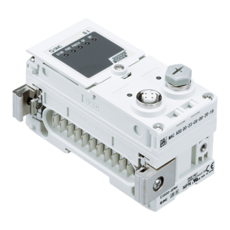
3 Name and function of parts
No
Part
Specifications
1
LED display
-10 to +50
o
C
2
Display cover
3
Display cover screw
-20 to +60
o
C
4
Connector (PORT 2)
5
Marker groove
6
Valve plate hole
7
Valve plate groove
300 g
8
Joint bracket
9
Unit connector
10 Connector (PORT 1)
Specifications
11 Seal cap (1 pc.)
24.0 VDC
2.0 A max.
24.0 VDC
2.0 A max.
120 mA maximum
PNP / source (negative
common)
32 outputs
4 Assembly
24 VDC and 1.0 W max.
4.1 Assembling the unit
Solenoid valve with surge
voltage suppression
(manufactured by SMC)
Do not install the product unless the safety instructions have been read
and understood.
(1) Connect an I/O unit to the end plate. Digital and analogue units can
Short circuit protection
be connected in any order. Joint bracket screw tightening torque: 1.5
to 1.6 N•m.
(2) Add more I/O units. Up to 9
I/O units can be connected
TM
to one manifold.
(3) Connect the SI unit. After
2 ports
connecting the required I/O
units, connect the SI unit.
The connection method is
as above.
(4) Mount
the
valve
(EX600-ZMV#) to the valve
manifold using the valve
screws (M3 x 8) supplied.
(Tightening torque: 0.6 to
0.7 N•m).
(5) Connect
the
SI
assembly
to
the
manifold.
TM
, Web server
Insert the valve plate into
the valve plate mounting
groove.
4 Assembly (continued)
Then fix using the valve plate mounting screws (M4 x 6) supplied
(Tightening torque: 0.7 to 0.8 N•m).
Description
5 Installation
Displays the SI unit status.
• Do not expose to direct sunlight. Use a suitable protective cover.
Display cover for switch setting.
• Do not install in a location subject to vibration or impact in excess of
To open the display cover.
the product's specifications.
Connector for Fieldbus Outputs.
• Do not mount in a location exposed to radiant heat that would result in
Groove for identification marker.
temperatures in excess of the product's specifications.
Hole for valve plate mounting.
• Direct mounting
Groove for valve plate mounting.
(1) When assembling six or more units, the middle part of the assembly
Bracket for joining to adjacent units.
must be fitted with an intermediate reinforcing brace (EX600-ZMB1)
Connector for signal/power to next unit.
before mounting using 2 - M4x5 screws (Tightening torque: 0.7 to 0.8
Connector for Fieldbus Inputs.
N•m).
For all unused M12 connectors
Warning
(2) Mount and tighten the end plate at one end of the unit and mount the
intermediate reinforcing brace if required using M4 screws
(Tightening torque: 0.7 to 0.8 N•m).
Fix the end plate at the valve side while referring to the operation
manual for the applicable valve series.
• DIN rail mounting
(1) When assembling six or more units, the middle part of the complete
assembly must be fitted with an intermediate reinforcing brace for DIN
rail mounting (EX600-ZMB2), using 2 - M4 x 6 screws.
(Tightening torque: 0.7 to 0.8 N•m).
(2) Mount the end plate bracket (EX600-ZMA2) to the end plate using 2-
M4 x 14 screws (Tightening torque: 0.7 to 0.8 N•m). For the SY
series, use end plate bracket (EX600-ZMA3).
plate
unit
valve
Page 1 of 3
Advertisement

Subscribe to Our Youtube Channel
Related Manuals for SMC Networks 56-EX600-SEN7-X10


Summary of Contents for SMC Networks 56-EX600-SEN7-X10
- Page 1 EX600-TF223-093EN 1 Safety Instructions (continued) 3 Name and function of parts 4 Assembly (continued) ORIGINAL INSTRUCTIONS • Protect the product from sources of heat which can generate surface Then fix using the valve plate mounting screws (M4 x 6) supplied temperatures greater than the temperature classification.
- Page 2 EX600-TF223-093EN 5 Installation (continued) 6 Settings 6 Settings (continued) 7 How to Order (3) Hook the DIN rail mounting groove on to the DIN rail. 6.1 Switch Settings Refer to the operation manual on the SMC website (URL: IO-Link master size Process data (4) Press the manifold using its side hooked to the DIN rail as a fulcrum IO size at each port...
- Page 3 EX600-TF223-093EN 9 LED Display (continued) 10 Maintenance 9.1 SI unit status 10.1 General Maintenance Caution LED Colour Operation The power supply for control and input is OFF. • Not following proper maintenance procedures could cause the product to malfunction and lead to equipment damage. Green ON Normal operation.
Need help?
Do you have a question about the 56-EX600-SEN7-X10 and is the answer not in the manual?
Questions and answers