Table of Contents
Advertisement
stellar.heatnglo.com
Custom Fireplace Program
Co-linear Direct Vent
Powervented Gas Fireplaces
ENLIGHT COLLECTION
SINGLE-SIDED
Installation and Operating Manual
NG & Propane
WARNING: If the information in these instructions are not followed exactly, a fire or explosion may result
causing property damage, personal injury or loss of life.
— Do not store or use gasoline or other flammable vapors and liquids in the vicinity of this or any other
appliance.
WHAT TO DO IF YOU SMELL GAS
—
•
Do not try to light any appliance.
•
Do not touch any electrical switch; do not use any phone in your building.
•
Immediately call your gas supplier from a neighbor's phone. Follow the gas supplier's instructions.
•
If you cannot reach your gas supplier, call the fire department.
— Installation and service must be performed by a qualified installer, service agency or the gas supplier.
DANGER
NEVER ALLOW CHILDREN
Stellar by Heat & Glo, a division of Hearth & Home Technologies
HOT GLASS WILL
CAUSE BURNS.
DO NOT TOUCH GLASS
UNTIL COOLED.
TO TOUCH GLASS.
Installer:
Leave this manual with the appliance.
Consumer: Retain this manual for future reference.
®
· 22160 Cedar Avenue Suite 200, Lakeville, MN 55044 · (952) 224 - 4072
Page 1
Advertisement
Chapters
Table of Contents

Subscribe to Our Youtube Channel
Related Manuals for Heat & Glo STELLAR 3-SS-20-G


Summary of Contents for Heat & Glo STELLAR 3-SS-20-G
- Page 1 stellar.heatnglo.com Custom Fireplace Program Co-linear Direct Vent Powervented Gas Fireplaces ENLIGHT COLLECTION SINGLE-SIDED Installation and Operating Manual NG & Propane Installer: Leave this manual with the appliance. Consumer: Retain this manual for future reference. WARNING: If the information in these instructions are not followed exactly, a fire or explosion may result causing property damage, personal injury or loss of life. — Do not store or use gasoline or other flammable vapors and liquids in the vicinity of this or any other appliance.
- Page 2 Read this manual before installing or operating this appliance. Please retain this owner’s manual for future reference. Congratulations on selecting a As the owner of a new fireplace, you’ll want to read Stellar by Heat & Glo gas fireplace. and carefully follow all of the instructions contained in this owner’s manual. You've selected a model within the Enlight Collection that is crafted to elevate even the most unique spaces.
- Page 3 UL RATING PLATE LOCATION & MODEL NUMBER IDENTIFICATION The rating plate is used for multiple designs and multiple collections, and custom fireplaces. The generic nomenclature listed on the rating plate will not identically match the model of Enlight fireplace you have. The rating plate must stay with the fireplace and is located below the burner in an area that will only be reachable while servicing.
-
Page 4: Table Of Contents
TABLE OF CONTENTS Section Description Page Section Description Page Introduction & Homeowners Reference Venting Continued 22-29 N. Vertical Cap Location & Clearances Table Of Contents O. Vertical Cap Location & Clearances - RS12/14/16 P. Vertical Cap Location & Clearances - RSIF160/180 Safety Information Q.1 Wall Termination Cap Installation Without Damper A. -
Page 5: Table Of Contents
TABLE OF CONTENTS Section Description Page Maintenance A. Vent System B. Glass Cleaning & Replacement Replacement Parts 58-60 A. Replacement Parts B. Glass Size & Specifications C. Horizontal & Vertical Glass Trim Pieces Service & Maintenance History - Basic Troubleshooting 61-63 Table For Documenting Service &... -
Page 6: Safety Information
1 - SAFETY INFORMATION This fireplace complies with ANSI Z21.50-2019/CSA 2.22-2019 Vented Gas Fireplaces and CAN/CSA P.4.1-15. Installation must conform with local building codes or in the absence of local building codes, with the National Fuel Gas Code, ANSIZ223.1/NFPA 54 - Current Edition, or the Natural or Propane Installation Code, CSAB149.1 A. SAFETY ICON DESIGNATIONS Various safety icons appear throughout this installation manual. Please familiarize yourself with the icons making sure you understand the serious consequences that may occur if ignored or of handling the products inappropriately. IMPORTANT NOTE HOT GLASS WARNING This indicates additional instructions that you should consider... -
Page 7: Commonwealth Of Massachusetts Requirements
2 - COMMONWEALTH OF MASSACHUSETTS REQUIREMENTS NOTE: THE FOLLOWING REQUIREMENTS REFERENCE VARIOUS MASSACHUSETTS AND NATIONAL CODES NOT CONTAINED IN THIS MANUAL. For all sidewall horizontally vented gas fueled equipment installed in every dwelling, building or structure used in whole or in part for residential purpos- es, including those owned or operated by the Commonwealth and where the side wall exhaust vent termination is less than (7) feet above finished grade in the area of the venting, including but not limited to decks and porches, the following requirements shall be satisfied: INSTALLATION OF CARBON MONOXIDE DETECTORS... -
Page 8: Specifications
3 - SPECIFICATIONS Finishing Finishing Height To Overall Overall B-VENT Model # Center Of Vent WEIGHT FLUE INTAKE Width Height Top Trim Height Width Ø Ø LBS/KG The dimensions in green are the allowable finishing width and height required to fit the glass into the fireplace; must not overlap onto glass. 3-SS-20-G 8"... - Page 9 3 - SPECIFICATIONS A. SINGLE SIDED DIMENSIONS Model 4-SS-24-G Shown In Example. The full shop drawing for each width FLUE B-VENT can be found under the RESOURCES tab at the stellar.heatnglo.com website. TOP VIEW 24 [610] [305] 3 [76] FRONT VIEW RECESSED 1 25/32 [45] 3 [76]...
-
Page 10: Installation Overview
3 - SPECIFICATIONS C. SPECIFICATIONS ORIFICE ORIFICE Model # B-VENT REG PV IN-LINE PV BTU’S Propane 8" 10" RS12 RSIF160 40,000 (2X) #43 (2X) #55 8” 10” RS12 RSIF160 60,000 (3X) #43 (3X) #55 8” 10” RS12 RSIF160 80,000 (4X) #43 (4X) #55 10”... -
Page 11: Fireplace Clearances To Combustibles
3 - SPECIFICATIONS F. FIREPLACE CLEARANCES TO COMBUSTIBLES INCHES MILLIMETERS From unit left & right sides [25] To flooring under fireplace Unit top to ceiling [152] Unit side to adjacent sidewall [25] CLEARANCES SHOWN ARE MINIMUM TO COMBUSTIBLES NON-COMBUSTIBLE FRAMING AND FINISHING MATERIALS ALLOWED RIGHT UP TO THE FIREPLACE. 1 [25] [25] 6 [152] Top Standoffs;... -
Page 12: Prepare The Fireplace
4 - PREPARE THE FIREPLACE CAUTION: FIREPLACE IS NOT LOAD-BEARING. NOTE: OTHER CLEARANCES APPLY. ALL CLEARANCES MUST BE MAINTAINED. A. STANDOFF INSTALLATION LOOSEN SCREW AND FOLD STANDOFF REMOVE SECOND SCREW LOOSENED SCREW PIVOT FOLDED STANDOFF AND SECURE Figure 4A.1 Figure 4A.2 STEP 1: Refer to Figure 4A.1 STEP 2: Refer to Figure 4A.2 The standoffs will be shipped in a flat state placed on the firebox top. Fold the center of the standoff up and both ends out at the perforated Locate the standoffs and loosen the screws holding them in place. - Page 13 4 - PREPARE THE FIREPLACE B. NAILING TABS Figure 4B.1 Figure 4B.2 Figure 4B.3 STEP 1: Refer to Figure 4B.1 STEP 2: Refer to Figure 4B.2 STEP 3: Refer to Figure 4B.3 & Figure 4B.4 The nailing tabs will be shipped in a flat state Bend the two (2) small tabs out on each Set each nailing tab in place and secure placed on the firebox sides. nailing tabs at the perforated lines.
-
Page 14: Important Framing Notes
5 - FRAMING & MANTEL REQUIREMENTS NOTE: Framing dimensions should allow for wall covering thickness and fireplace facing materials. When using a hearth, adjust rough opening size as necessary to maintain at least minimum clearance requirements. CAUTION: Install fireplace on metal, concrete or hard wood surface extending the full width and depth of fireplace. CAUTION: Vent cap location must be in compliance with guidelines in Section 8 (Venting) of this manual. NOTE: REFER TO DIMENSIONS SECTION FOR ALLOWABLE FINISHING DIMENSIONS REQUIRED TO FIT THE GLASS PANELS INTO THE FIREPLACE. FINISHING MATERIALS MUST NOT OVERLAP THE DIMENSIONS HIGHLIGHTED IN GREEN IN SECTION 2 (DIMENSIONS). NEVER COVER THE GLASS WITH FINISHING MATERIALS. - Page 15 5 - FRAMING & MANTEL REQUIREMENTS NOTE: IT IS RECOMMENDED TO SET THE FIREPLACE IN TO PLACE PRIOR TO INSTALLING THE FRAMING. Framing dimensions noted are minimum framing dimensions to combustible materials only, and it is the responsibility of the installer for determining framing dimensions that allow for wall covering thickness and fireplace facing materials for each individual installation. inches [mm] Figure 5A Dimensions assume the 1/2"...
- Page 16 5 - FRAMING & MANTEL REQUIREMENTS B.1 NON-COMBUSTIBLE ZONE - USING THE PROVIDED 1/2" STANDOFFS The fireplace has standoffs installed on the front of the fireplace standard from the factory. They are located on the INCHES [MM] upper left, center and right front of the fireplace and are to ensure that the 1/2 [13] required clearance to combustibles on the surface of the fireplace is maintained.
- Page 17 5 - FRAMING & MANTEL REQUIREMENTS B.2 NON-COMBUSTIBLE ZONE - NOT USING THE PROVIDED 1/2" STANDOFFS The fireplace has standoffs installed on the front of the fireplace standard from the factory. They are located on the left, INCHES [MM] center and right front hood of the fireplace and are to ensure that the 1/2[13] required clearance to combustibles on the surface of the fireplace is maintained.
-
Page 18: Glass Frame Assembly
6 - GLASS FRAME ASSEMBLY A. GLASS FRAME ASSEMBLY IDENTIFICATION GLASS GLASS Upper Groove Quality Suction Cup LOWER FILLER STRIP SITS OVER GLASS CLIPS LOWER FILLER STRIP SITS OVER GLASS CLIPS Lower Groove GLASS CLIP GLASS CLIP Figure 6B.1 Figure 6A CAUTION: TO PREVENT GLASS FRAME ASSEMBLY FROM FALLING FROM FIREPLACE AND BECOMING DAMAGED, FOLLOW THE INSTRUCTIONS EXACTLY WHEN REMOVING AND INSTALLING GLASS FRAME ASSEMBLY. -
Page 19: Install Glass Frame Assembly/Glass Edge Protectors
6 - GLASS FRAME ASSEMBLY Refer to Section 6 (Glass Frame Assembly Identification Figures 6A & 6B.1) when installing and removing the glass frame assembly. B. INSTALL GLASS FRAME ASSEMBLY IMPORTANT: PLASTIC GLASS EDGE PROTECTORS The fireplace is shipped with a plastic edge protector on the outer pane of glass only. U-Shaped See Figure 6B.2 Edge Top/Bottom Glass Pane Protector Inner Glass Figure 6B.2 - Outer Glass Edge Protector Unwrap the panes of glass carefully making sure to protect the edges. -
Page 20: Gas Line Specifications & Connection
7 - GAS LINE SPECIFICATIONS This fireplace is manufactured for use with Natural Gas or Propane. CAUTION: Installation of the gas line must only be done by a qualified person in accordance with local building codes, if any. If not, follow ANSI 223.1. NOTE: The appliance and its individual shutoff valve must be disconnected from the gas supply piping system during any pressure testing of that system at pressures in excess of ½ psi. NOTE: The appliance must be isolated from the gas supply piping system by closing its individual manual shut-off valve during any pressure testing of the gas line at test pressures equal to or less than ½ psi (3.5 kPa). NOTE: For high altitude installations, consult Stellar by Heat&Glo directly for proper rating methods. A. GAS LINE CONNECTION Propane 11.0 inches W.C. 7.0 inches W.C. MINIMUM INLET GAS PRESSURE (recommended) (recommended) MAXIMUM INLET GAS PRESSURE 14.0 inches W.C. 10.0 inches W.C. MANIFOLD PRESSURE (HI) 10.0 inches W.C. 3.5 inches W.C. -
Page 21: Gas & Electric Access Locations
7 - GAS LINE SPECIFICATIONS B. GAS & ELECTRIC ACCESS LOCATIONS 4' shown in example. Locations/dimensions are the same on all models and all sizes. PILOT SIDE VIEW BACK SIDE VIEW ELECTRIC ELECTRIC 3” GAS 3” GAS 2X 2 27/32" 1 1/2" 1 25/32" 1 1/2" 2X 1 19/32" 2 3/4" 2 7/32" 3 7/32" 2 7/32" 5 13/32"... -
Page 22: Venting
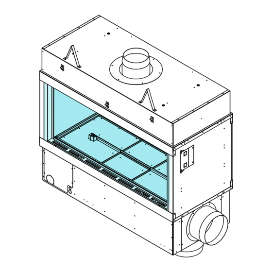
8 - VENTING CAUTION: Consult the local and national installation codes to assure adequate combustion and ventilation air is available. NOTE: Flame height and appearance will vary depending upon venting configuration and type of fuel used. Venting requirements apply to both Natural and Propane gas. STOP: MAINTAIN ALL CLEARANCES AS STATED IN THIS INSTALLATION MANUAL. Figure 7 A. APPROVED VENTING B.1 SYSTEM SUPPLY VOLTAGE OUTSIDE B-VENT STANDARD AMPS POWERVENT MODEL NUMBER IN-LINE Model # DESCRIPTION Ø POWERVENT POWERVENT Ø RS12 (3', 4', & 5' Models) ANY HEIGHT 8"... -
Page 23: Rs Series Powervent Specifications
8 - VENTING C. RS SERIES POWERVENT SPECIFICATIONS Available Power Venting A power vent (RS12 & RS14) is approved for use with this appliance. It is crucial that all B-Vent pipe and elbow joints, and the longitudinal seam are sealed using a high temperature RTV Silicone and/or foil tape. MODEL RS12 RS14... -
Page 24: Rsif Series Powervent Specifications
8 - VENTING E. RSIF SERIES POWERVENT SPECIFICATIONS Available In-Line Power Venting An in-line power vent (RSIF series from Enervex) is approved for use with Stellar fireplaces. Vent runs after the in-line powervent may use a pressure approved pipe, but it is not required. If you use B-Vent after an in-line powervent it is crucial that all pipe and elbow joints, and the longitudinal seam are sealed using an high heat approved mastic or foil tape. -
Page 25: In-Line Powervent Preparations- Rsif 180
8 - VENTING F. IN-LINE POWERVENT PREPARATIONS- RSIF 180 Perform the following steps when installing the RSIF180 on 6', 7' & 8' models. Attach the provided 10 inch B-Vent collar to the intake side of the powervent. The intake side is located opposite the fan motor as shown in Figure 8F.1. -
Page 26: Horizontal Vent System Clearance
8 - VENTING G. HORIZONTAL VENT SYSTEM CLEARANCES ALL APPROVED VENTING BOTTOM SIDES HORIZONTAL 1 [25] 1 [25] 1 [25] inches [mm] H. WALL PASS-THROUGH - Follow all local codes for requirement of firestops. 8 - VENTING I. PITOT TUBE INFORMATION Figure 8I There is a 1/4" pitot tube mounted in the center of the flue collar and is connected to the pressure switch. -
Page 27: Vertical Terminations Guidelines
8 - VENTING J.VERTICAL TERMINATION GUIDELINES • The fireplace must terminate with the included approved powered termination cap. • NO SUBSTITUTION IS ACCEPTABLE. • Carefully follow the instructions included with the approved powered termination cap. DO NOT use an additional speed control on this powervent. • • You must use the included Capacitor. K. HORIZONTAL TERMINATION VENT CAP LOCATION & CLEARANCE This gas appliance must not be connected to a chimney serving any other appliance. • DO NOT RECESS TERMINATION KIT INTO OUTSIDE BUILDING MATERIALS - i.e.: brick, stone, siding, etc. If necessary, extend framing so that termination kit will be exposed once building materials are installed. - Page 28 8 - VENTING L. HORIZONTAL TERMINATION VENT CAP LOCATION & CLEARANCES Inside Corner Outside Corner Recessed Location A = Combustible 24” (609.6mm) F = Combustible 6” (152mm) = Non-combustible 6” (152mm) = Non-combustible 12” (304.8mm) Balcony Balcony with perpendicular side wall with no side wall C = Clearance from corner in recessed location = Combustible 24”...
- Page 29 8 - VENTING M. HORIZONTAL POWERVENT AND AIR-INTAKE PLACEMENT CLEARANCES M.1 - RS SERIES POWERVENT M.2 - IN-LINE POWERVENT (LOUVER 8/10) X = Intake X = Intake PV = Vent PV = Vent P.V. 36 [914] 24 [610] [610] [610] 24 [610] inches [mm] inches [mm] Minimum Clearance Using an In-Line Powevent Minimum Clearance Using a RS Series Powervent Intake Placed Below Vent = 24 [610] Intake Placed Above Vent = 36 [914]...
- Page 30 8 - VENTING N. VERTICAL VENT CAP LOCATION AND CLEARANCES ROOF PITCH H (Min.) Ft. H (Min.) M. FLAT TO 6/12 1.0* 0.30 OVER 6/12 TO 7/12 1.25* 0.38 OVER 7/12 TO 8/12 1.5* 0.46 OVER 8/12 TO 9/12 2.0* 0.61 OVER 9/12 TO 10/12 2.5* 0.76 OVER 10/12 TO 11/12 3.25* 0.99 OVER 11/12 TO 12/12 1.22 OVER 12/12 TO 14/12 1.52 OVER 14/12 TO 16/12 1.83 OVER 16/12 TO 18/12 2.13 * = 3 foot minimum in OVER 18/12 TO 20/12 2.27...
- Page 31 8 - VENTING P. VERTICAL -CLEARANCES -RSIF160-180 O. VERTICAL -CLEARANCES - RS12/14/16 Figure 8O Figure 8P Page 31 INS_16400-7800 Rev B ENLIGHT SINGLE-SIDED...
- Page 32 8 - VENTING Q. WALL TERMINATION - WITH AND WITHOUT DAMPER Wall Termination Without Optional Mechanical Damper FRAMING: 8" = 11-3/4 [298] W X 11-3/4 [298] H 10" = 13-1/4 [337] W X 13-1/4 [337] H Drill 1/4” holes to match powervent base Insulation Pad Must be cut in center to accommodate vent size...
- Page 33 8 - VENTING R. ROOF TERMINATION CAP INSTALLATION - WITH AND WITHOUT DAMPER Roof Termination Without Optional Mechanical Damper Powervent Mounting Brackets or drill mounting holes to match base Insulation Pad Must be cut in center to accommodate vent size Steel chimney adapter Figure 8R.1 Roof Termination With...
- Page 34 8 - VENTING S. CHASE TOP CAP INSTALLATION - WITH AND WITHOUT DAMPER Roof Termination Without Optional Mechanical Damper Powervent Insulation Pad Must be cut in center to accommodate vent size Steel Chimney Adapter Bend inner flanges up to slide inside the chimney collar plate.
-
Page 35: Chimney Shroud Types & Specifications
8 - VENTING T. CHIMNEY SHROUD TYPES AND SPECIFICATIONS NON-COMBUSTIBLE CONSTRUCTION ONLY ALLOWED TOP CLOSED 50% OPEN IN TOP 3 [76] OF SHROUD TOP MUST BE OPEN MUST BE REMOVABLE FOR SERVICE 6 [152] 6 [152] 6 [152] 6 [152] &... - Page 36 8 - VENTING U. OUTDOOR AIR INTAKE This fireplace has the options of air intake connections on the side or the bottom of the fireplace. This fireplace is approved for use with 10 inch rigid metal pipe or UL approved 10 inch Class 0 or Class 1 flex for intake air. Use Table 8U.1 for venting requirements if using UL approved 10 inch flex for intake air.
- Page 37 8 - VENTING V. CHANGING FROM OUTSIDE SIDE INTAKE AIR TO BOTTOM INTAKE AIR Step 1: Remove 4 screws that hold collar plate in place. Step 2: Slide collar plate off fireplace. Refer to Figure 8V.1 Refer to Figure 8V.2 Remove 4 Screws Figure 8V.1...
-
Page 38: Room Air For Combustion - Toe Kick Example
8 - VENTING W. ROOM AIR FOR COMBUSTION - TOE KICK EXAMPLE WITHOUT HEARTH SINGLE SIDE INTAKE WITHOUT HEARTH EXTENSION If drawing air from the room, the appropriate NOT APPLICABLE TO OPEN HEARTH INSTALLATIONS amount of make-up air must be introduced to replace the air taken from the room. - Page 39 8 - VENTING X ROOM AIR FOR COMBUSTION - TOE KICK EXAMPLE WITH HEARTH SINGLE SIDE INTAKE WITH HEARTH EXTENSION NOT APPLICABLE TO OPEN HEARTH INSTALLATIONS Follow this template on at least one long side of multiside units. 3’-7’ = 18.5 [470] 8’...
-
Page 40: Vertical Air-Intake Side Chute
9- VENTING OPTIONS NOTE: CANNOT USE ON BAY OR FOUR SIDED DESIGNS A. OPTIONAL VERTICAL AIR-INTAKE SIDE CHUTE Use of the optional Outdoor Air-Intake Side Chute may be used with vertical runs where space is limited on the side of the fireplace. COLLAR inches [mm] WIDTH... - Page 41 9- VENTING OPTIONS B. OPTIONAL UNIVERSAL EXHAUST IN AIR-INTAKE LOUVER MODEL UNITS LOUVER-8 3', 4' & 5' Exhaust Only LOUVER-10 3', 4' & 5' Air-Intake LOUVER-10 6', 7' Exhaust and Air-Intake LOUVER-10 Exhaust Only LOUVER-12 Air-Intake ONLY • This kit is an optional method of terminating the fresh air and/or exhaust for the appliance.
-
Page 42: Electrical Installation Overview
10 - ELECTRIC For Tethered Control Panel Refer To Section 10 (D, E.1 & E.2) A. ELECTRICAL INSTALLATION OVERVIEW POWERVENT ENERVEX RS09- RS16 WHIP INCLUDED POWERVENT CAP INSULATION PAD CUT HOLE IN PAD EQUAL TO OR GREATER THAN THE FLUE DIAMETER ADAPTER PLATE FLUE PIPE WHIP... - Page 43 10 - ELECTRIC B.1. ELECTRICAL WIRING SCHEMATIC - TROUBLESHOOTING NOTE: The appliance, when installed, must be electrically grounded in accordance with local codes or, in the absence of local codes, with the National Electrical Code, ANSI/NFPA 70, or the Canadian Electrical Code, Part 1, CSA C22.1. Figure 10 B.1 Page 43 INS_16400-7800 Rev B ENLIGHT SINGLE-SIDED...
- Page 44 10 - ELECTRIC B.2 ELECTRICAL WIRING SCHEMATIC - FIELD WIRE THE FIREPLACE TO A 15 AMP MIN DEDICATED CIRCUT. SEE TERMINALS #5 & #6. Supply Powervent Voltage Chart (N/L1) Voltage Chart RS12 RS12 RS14 RS14 RSIF160 RSIF160 RSIF180 13/16 RSIF180 To light the fireplace: Activate the switch.
-
Page 45: Junction Box & Capacitor
10 - ELECTRIC B.3 JUNCTION BOX & CAPACITOR C.1 TERMINALS 1 & 2 - LED LIGHTING DO NOT DISCARD TERMINAL 1 & 2: LED LIGHTING JUNCTION BOX - CAPACITOR INSIDE HAS 120VAC POWER TO SUPPLY A SWITCH, RELAY, TIMER, TERMINAL #2 REMOTE, ETC. RETURNS 120VAC POWER TO ACTIVATE THE LED DRIVER. - Page 46 10 - ELECTRIC C.2 TERMINALS 3 & 4 - MAIN FLAME TERMINAL 3 & 4 : MAIN FLAME TERMINAL #4 HAS 120VAC POWER TO SUPPLY A SWITCH, RELAY, TIMER, TERMINAL #4 REMOTE, ETC. TERMINAL #3 RETURNS 120VAC POWER TO ACTIVATE TO MAIN FLAMES. TERMINAL #3 IF USING STANDARD ROMEX, CONNECT BLACK TO TERMINAL #4 AND WHITE TO TERMINAL #3. SINCE 120 VOLTS WILL TRAVEL ON WHITE, MARK THE WHITE WIRE ACCORDING TO CODE.
- Page 47 10 - ELECTRIC C.3 - TERMINALS 5 & 6 C. 4 - TERMINALS 7 & 8 FIREPLACE POWER POWERVENT MOTOR TERMINAL 5 & 6: FIREPLACE POWER TERMINAL 7 & 8: POWERVENT CONNECTION POWERVENT POWER MUST COME FROM THE TERMINAL BLOCK AND GROUND - LOCATE THE GREEN WIRE CLUSTER NOT ANY OTHER POWER SOURCE. CONNECT THE GREEN WIRE TAIL TO BUILDING GROUND IS THE HOT CONNECTION FOR THE POWERVENT MOTOR FROM TERMINAL #8...
-
Page 48: Terminals 9 & 10: Flue Damper Connection
10 - ELECTRIC C.5 - TERMINALS 9 & 10 C. 6 - TERMINALS 11 & 12 FLUE DAMPER CONNECTION FLUE DAMPER PROVE TERMINALS 11 & 12: FLUE DAMPER PROVE TERMINALS 9 & 10: FLUE DAMPER CONNECTION THIS IS LOW VOLTAGE AND EXTERNAL POWER MUST NOT BE APPLIED THIS IS LOW VOLTAGE AND EXTERNAL POWER MUST NOT BE APPLIED S THE NEUTRAL CONNECTION FOR THE DAMPER MOTOR. -
Page 49: Tethered Control Panel Installation Overview
10 - ELECTRIC For Standard Electric Installation Refer To Seciton 10 (A.1 - C.6) D. TETHERED CONTROL PANEL INSTALLATION OVERVIEW POWERVENT ENERVEX RS09- RS16 WHIP INCLUDED POWERVENT CAP INSULATION PAD CUT HOLE IN PAD EQUAL TO OR GREATER THAN THE FLUE DIAMETER ADAPTER PLATE FLUE PIPE WHIP... - Page 50 10 - ELECTRIC E.1 ELECTRICAL WIRING SCHEMATIC - FIELD WIRING WIRE THE FIREPLACE TO A 15 AMP MIN DEDICATED CIRCUT. SEE TERMINALS #5 & #6. Powervent Supply Shown With Enervex RS Series Powervent Voltage Chart Voltage Chart (N/L1) and Optional Flue Damper RS12 RS12 RS14...
- Page 51 10 - ELECTRIC E.2 ELECTRICAL WIRING SCHEMATIC - TROUBLESHOOTING SYSTEM: TB1B111SYS Figure 10 E.2 DENOTES LOW VOLTAGE DENOTES NEUTRAL FIREPLACE FLUE PRESSURE SWITCH CONTROLLER INTAKE DAMPER PURPLE BLACK ORANGE BLUE YELLOW PURPLE YELLOW GAS VALVE BLUE 12VDC BLACK SPEED CONTROL TIMER RELAY PURPLE OPTIONAL FLUE DAMPER PROVE...
-
Page 52: Finishing
11 - FINISHING A.1 FINISHING THE WALL - USING THE PROVIDED 1/2" STANDOFFS NOTE: REFER TO DIMENSIONS SECTION FOR ALLOWABLE FINISHING DIMENSIONS REQUIRED TO FIT THE GLASS PANELS INTO THE FIREPLACE. FINISHING MATERIALS MUST NOT OVERLAP THE DIMENSIONS HIGHLIGHTED IN GREEN ON PAGE 5. NEVER COVER THE GLASS WITH FINISHING MATERIALS. NOTE: DO NOT PIERCE ANY OF THE BLACK PAINTED SURFACES WITH SCREWS, RIVETS, ETC. THIS INCLUDES THE 3" [76mm] BLACK TOP AND BOTTOM GLASS TRIM AND ANY PAINTED SIDES ADJACENT TO THE GLASS. NOTE: REFER TO MANTEL REQUIREMENTS: NON-COMBUSTIBLE ZONE USING PROVIDED 1/2"... - Page 53 11 - FINISHING A.2 FINISHING THE WALL - NOT USING THE PROVIDED 1/2" STANDOFFS NOTE: REFER TO DIMENSIONS SECTION FOR ALLOWABLE FINISHING DIMENSIONS REQUIRED TO FIT THE GLASS PANELS INTO THE FIREPLACE. FINISHING MATERIALS MUST NOT OVERLAP THE DIMENSIONS HIGHLIGHTED IN GREEN ON PAGE 5. NEVER COVER THE GLASS WITH FINISHING MATERIALS. NOTE: DO NOT PIERCE ANY OF THE BLACK PAINTED SURFACES WITH SCREWS, RIVETS, ETC. THIS INCLUDES THE 3" [76mm] BLACK TOP AND BOTTOM GLASS TRIM AND ANY PAINTED SIDES ADJACENT TO THE GLASS.
-
Page 54: Lighting & Shutdown
12 - LIGHTING & SHUTDOWN FOR YOUR SAFETY - READ BEFORE LIGHTING STOP: IF YOU DO NOT FOLLOW THESE INSTRUCTIONS EXACTLY, A FIRE OR EXPLOSION MAY RESULT, CAUSING PROPERTY DAMAGE, PERSONAL INJURY OR LOSS OF LIFE. UE TO HIGH SURFACE TEMPERATURES, KEEP CHILDREN, CLOTHING AND FURNITURE AWAY. This appliance needs fresh air for safe operation and must be installed so there are provisions for adequate combustion and ventilation air. It is important to make sure the termination cap remains unobstructed at all times from snow, ice, leaves or other debris. •... -
Page 55: If The Fireplace Does Not Light
12 - LIGHTING & SHUTDOWN STOP! Read safety information on previous page and front cover of this manual before continuing. NOTE: This fireplace is equipped with an ignition device which automatically lights the pilot. DO NOT try to light the pilot by hand. B. IF THE FIREPLACE DOES NOT LIGHT Turn off the fireplace at switch. Turn off all electrical power to fireplace. Wait five (5) minutes to allow any gas that may have accumulated inside firebox to escape. -
Page 56: Inlet Pressure Testing
13 - PRESSURE TESTING NOTE: The appliance and its individual shutoff valve must be disconnected from the gas supply piping system during any pressure testing of that system at pressures in excess of ½ psi. NOTE: The appliance must be isolated from the gas supply piping system by closing its individual manual shut-off valve during any pressure testing of the gas line at test pressures equal to or less than ½ psi (3.5 kPa). INLET PRESSURE TEST The valve has an Allen-plug on the inlet and outlet. Install a barb fitting on the tap you want to measure. Light the fireplace, check the pressure. Turn off fireplace; reinstall plug. Check for leaks. -
Page 57: Maintenance
15 - MAINTENANCE The appliance is required to be inspected at least once a year by a professional service person. The compartment below firebox (behind lower access panel) must be cleaned at least once a year, more frequent cleaning may be required due to excessive lint from carpeting, bedding materials, or other fibrous materials. It is imperative that the burner be cleaned once a year. VALVE AND ELECTRICAL ACCESS There is an access panel under the floor of the firebox should more extensive service be needed. Remove the inner and outer glass panels. Remove the glass media on the end with the pilot. The end floor lifts out; remove the screws and lift it out. If the LED’s are mounted on a “U” shaped steel bracket, loosen the bracket and flip the LED’s over the burner. There is a panel covering the valve area. Remove the screws and lift the panel up and out to expose the valve area. NOTE: INSTALLATION AND REPAIR SHOULD BE DONE ONLY BY QUALIFIED SERVICE PERSON. THE APPLIANCE SHOULD BE INSPECTED BEFORE USE AND ANNUALLY BY A QUALIFIED SERVICE PERSON. -
Page 58: Replacement Parts
16- REPLACEMENT PARTS A. REPLACEMENT PARTS LIST IMPORTANT: REPLACEMENT PARTS Parts must be ordered from a dealer or distributor. Hearth & Home Technologies does not sell directly to consumers. Provide model number and serial number when requesting service parts from your dealer or distributor. PART PART NUMBER PART... -
Page 59: Glass Size & Specifications
16- REPLACEMENT PARTS B. GLASS SIZE AND SPECIFICATIONS NOTE: IN CASE OF CHIPPED OR BROKEN GLASS Due to the size and sensitivity of shipping the glass separately, it is best to have the replacement glass cut locally if needed using the specifications listed here or have your local dealer assist you with contacting Stellar by Heat&Glo directly for more information. B. Glass Width Model B - WIDTH Width 37-7/16 [951] 49-7/16 [1,256] 61-7/16 [1,561] 73-7/16 [1,865] 85-7/16 [2,170] 97-7/16 [2,475] Inner Glass & Outer Glass The Same Size 1/4 [6.35] A. - Page 60 16- REPLACEMENT PARTS C. GLASS TRIM PIECES IDENTIFICATION Figure 16C PILOT A = Horizontal Trim Pieces B= Vertical Trim Pieces B. Vertical Trim A. Horizontal Trim Model Model Height Width 20" SRV16400-1433 SRV16300-1144 24" SRV16400-1033 SRV16400-1144 30" SRV16400-1633 SRV16500-1144 36" SRV16400-1833 SRV16600-1144 48"...
- Page 61 17 - SERVICE & MAINTENANCE HISTORY Service & Maintenance History Provided By Date: Description of Service Name Figure 17 Page 61 INS_16400-7800 Rev B ENLIGHT SINGLE-SIDED...
- Page 62 Page 62 INS_CUST UL REV E...
- Page 63 Page 63 INS_16400-7800 Rev B ENLIGHT SINGLE-SIDED...
- Page 64 Subordinate New Brand 3 in 1 LED Controller ( 2.4G ) Instruc�on Manual Contents Product features ..................2 Set up output mode ................3 Compa�ble with remote ................ 3 2.4G RF remote control instruc�on ............ 4-7 ..............4 Link / Unlink Instruc�ons ...........
-
Page 65: Product Features
Product features Made by new 2.4GHz wireless transmi�ng technology with low power consump�on, strong ability to build network automa�cally and an�-interference. with MiBoxer 2.4GHz gateway to get wireless dimming color, remote control, �ming control, group control, music rhythm func�on. Support 2.4G RF remote control. 16 Millions of colors to choose Color temperature adjustable Dim brightness / Satura�on... -
Page 66: Set Up Output Mode
Set up output mode Set up correct output mode based on the feature of lights Se�ng method: Press "SET" bu�on con�nuously to switch output mode (a�en�on: it will log out without opera�on within 3 seconds) Output mode sheet ( confirm output mode based on color of indicator) Indicator color Red Light Green Light... -
Page 67: G Rf Remote Control Instruc�On
2.4G RF Remote control instruc�on 1). Linking Code Instruc�ons Power Light Power Light Link / Unlink bu�on Power off 10 seconds and Short press " I " bu�on Lights blink 3 �mes power on again or short 3 �mes within 3 seconds. slowly means linking press "SET"... -
Page 68: Auto Transmi�Ng & Synchroniza�On
3). Auto transmi�ng & Synchroniza�on (only for remote control) Remote signal auto transmi�ng One light can transmit the signals from the remote control to another light within 30m, as long as there is a light within 30m, the remote control distance can be limitless. - Page 69 Dynamic mode table 2 (need to switch manually) Number Dynamic Mode Brightness / Satura�on / Speed Seven colors gradual change White light Gradual change RGB gradual change Seven colors jump to change Jump to change randomly Adjustable Red light gradual change +Flash 3 �mes Green light gradual change +Flash 3 �mes...
-
Page 70: Do Not Disturb" Mode Is Ac�Vated And Shut Down
6). “Do Not Disturb” mode is ac�vated and shut down (default ac�vated) Turn on “Do Not Disturb” mode (wide using in the area which have power failure frequently to save energy) 2.4G RF Remote turn on and turn off instruc�on Turn on “Do Not Disturb”... -
Page 71: Dmx512 Led Transmi�Er Control Instruc�On
DMX512 LED Transmi�er Control (Purchased separately) Only for RGB+CCT output mode Limitless Zone DMX512 Transmi�er Zone Limitless Connect DMX512 LED Transmi�er Link/Unlink Follow instruc�on of DMX512 transmi�er (FUTD01), Choose the zone for the light by pressing “ + ” or “ - ” (e.g. “CH12” means zone 12) Link/Unlink bu�on Power Power... -
Page 72: A�En�On
A�en�on 1. Please turn off power supply before installa�on. 2. Please ensure input voltage to be same as requirements from device. 3. Don’t disassemble device if you are not expert, otherwise it will damage it. 4. Please do not use the light in the place with widely range metal area or strong electromagne�c wave nearby, otherwise, the remote distance will be seriously affected. - Page 73 Hearth & Home Technologies LLC LIMITED LIFETIME WARRANTY Hearth & Home Technologies LLC (“HHT”) extends the following warranty for HHT gas, wood, pellet and electric hearth appliances (each a “Product” and collectively, the “Product(s)”) and certain component parts set forth in the table below (“Component Part(s)”) that are purchased from a HHT authorized dealer or distributor.
- Page 74 WARRANTY CONDITIONS: • Because HHT cannot control the quality of any Products sold by unauthorized sellers, this Warranty only covers Products that are purchased through an HHT authorized dealer or distributor unless otherwise prohibited by law; a list of HHT authorized dealers is available on the HHT branded websites.
Need help?
Do you have a question about the STELLAR 3-SS-20-G and is the answer not in the manual?
Questions and answers