Table of Contents
Advertisement
Model:
Escape-36DV
WARNING: IF THE INFORMATION
IN THESE INSTRUCTIONS IS NOT
FOLLOWED EXACTLY, A FIRE OR
EXPLOSION MAY RESULT CAUS-
ING PROPERTY DAMAGE, PER-
SONAL INJURY, OR DEATH.
- Do not store or use gasoline or other flam-
mable vapors and liquids in the vicinity of this
or any other appliance.
- What to do if you smell gas
• Do not try to light any appliance.
• Do not touch any electrical switch.
• Do not use any phone in your building.
• Immediately call your gas supplier from a
neighbor's phone. Follow the gas supplier's
instructions.
• If you cannot reach your gas supplier, call
the fire department.
- Installation and service must be performed by a
qualified installer, service agency, or the gas
supplier.
Printed in U.S.A. Copyright 2003,
Heat-N-Glo, a brand of Hearth & Home Technologies Inc.
20802 Kensington Boulevard, Lakeville, MN 55044
This product is covered by one or more of the following patents: (United States) 4,112,913; 4,408,594; 4,422,426; 4,424,792; 4,520,791; 4,793,322;
4,852,548; 4,875,464; 5,000,162; 5,016,609; 5,076,254 5,191,877; 5,218,953; 5,328,356; 5,429,495; 5,452,708; 5,542,407; 5,613,487; (Australia)
543790; 586383; (Canada) 1,123,296; 1,297,746; 2,195,264; (Mexico) 97-0457; (New Zealand) 200265; or other U.S. and foreign patents pending.
READ THIS MANUAL BEFORE INSTALLING OR
OPERATING THIS APPLIANCE. THIS INSTALLERS
GUIDE MUST BE LEFT WITH APPLIANCE FOR
FUTURE REFERENCE.
WARNING: IMPROPER INSTALLA-
TION, ADJUSTMENT, ALTERATION,
SERVICE OR MAINTENANCE CAN
CAUSE INJURY OR PROPERTY DAM-
AGE. REFER TO THIS MANUAL. FOR
ASSISTANCE OR ADDITIONAL INFOR-
MATION CONSULT A QUALIFIED IN-
STALLER, SERVICE AGENCY , OR THE
GAS SUPPLIER.
1. This appliance may be installed in an af-
termarket, permanently located, manufac-
tured (mobile) home, where not prohibited
by local codes.
2. This appliance is only for use with the type
of gas indicated on the rating plate. This
appliance is not convertible for use with
other gases, unless a certified kit is used.
Please contact your Heat-N-Glo dealer with any
questions or concerns. For the number of your nearest
Heat-N-Glo dealer, please call 1-888-427-3973.
1
Installers Guide
Underwriters
Laboratories Listed
2012-900E 11/03
Advertisement
Table of Contents

Subscribe to Our Youtube Channel
Related Manuals for Heat & Glo 36DV


Summary of Contents for Heat & Glo 36DV
- Page 1 Model: Escape-36DV WARNING: IF THE INFORMATION IN THESE INSTRUCTIONS IS NOT FOLLOWED EXACTLY, A FIRE OR EXPLOSION MAY RESULT CAUS- ING PROPERTY DAMAGE, PER- SONAL INJURY, OR DEATH. - Do not store or use gasoline or other flam- mable vapors and liquids in the vicinity of this or any other appliance.
-
Page 2: Safety And Warning Information
SAFETY AND WARNING INFORMATION READ and UNDERSTAND all instructions carefully before starting the installation. FAILURE TO FOLLOW these installation instructions may result in a possible fire hazard and will void the warranty. Prior to the first firing of the fireplace, READ the Using Your Fireplace section of the Owners Guide. -
Page 3: Table Of Contents
TABLE OF CONTENTS Safety and Warning Information ... 2 Service Parts Lists ... 4 Section 1: Approvals and Codes ... 6 Appliance Certification ... 6 Installation Codes ... 6 High Altitude Installations ... 6 Section 2: Getting Started ... 7 Introducing the Heat-N-Glo Gas Fireplaces ... -
Page 4: Service Parts Lists
(NG, LP) Exploded Parts Diagram (GN, PL) Vue éclatée des pièces VELCRO * Part number list on following page. * La liste des numéros de pièce se trouve à la page suivante. ESCAPE-36DV Beginning Manufacturing Date: 9-03 Ending Manufacturing Date: ______ Log set assembly... - Page 5 LP Conversion Kit / Module de conversion PL *NOTE: Replacement bulbs to be supplied by homeowner. Recommended replacements: Sylvania Mini Candelabra 75 watts. See Section 4: Maintaining and Servicing your Fireplace for instructions. DESCRIPTION ESCAPE-36DV PART NUMBER / N° DE PIÈCE SRV750-706...
-
Page 6: Section 1: Approvals And Codes
Appliance Certification The Heat-N-Glo fireplace model discussed in this Installers Guide has been tested to certification standards and listed by the applicable laboratories. Certification MODEL: ESCAPE-36DV LABORATORY: Underwriters Laboratories TYPE: Direct Vent Gas Fireplace Heater STANDARD: ANSI Z21.88-2000•CSA2.33-M98•UL307B Installation Codes The fireplace installation must conform to local codes. -
Page 7: Section 2: Getting Started
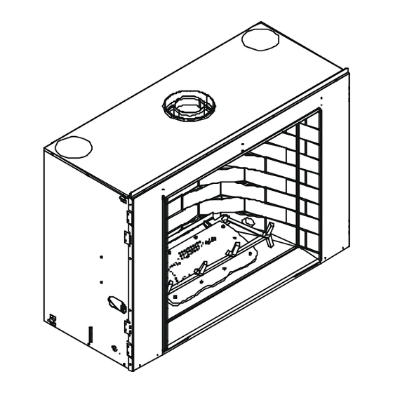
Getting Started Introducing the Heat-N-Glo Gas Fireplaces Heat-N-Glo direct vent gas fireplaces are designed to oper- ate with all combustion air siphoned from outside of the building and all exhaust gases expelled to the outside. The information contained in this Installers Guide, unless noted otherwise, applies to all models and gas control systems. - Page 8 GAS LINE 54-1/8” ACCESS (1375mm) 2-5/8” (66mm) 11-5/8” (295mm) 4-1/4” ELECTRICAL ACCESS (106mm) GAS LINE ACCESS CONTROLS Figure 1. Diagram of the ESCAPE-36DV 25-3/8” (646mm) 12” (304mm) 50-7/8” 1” (25mm) (1292mm) 35-1/2” (900mm) 36” (914mm) TOP VENT COLLARS RATNG PLATES AND LABELS Ø8”...
-
Page 9: Section 3: Installing The Fireplace
Installing the Fireplace Constructing the Fireplace Chase A chase is a vertical box-like structure built to enclose the gas fireplace and/or its vent system. Vertical vents that run on the outside of a building may be, but are not required to be, installed inside a chase. -
Page 10: Step 2 Framing The Fireplace
Step 2. Framing the Fireplace Fireplace framing can be built before or after the fireplace is set in place. Framing should be positioned to accommo- date wall coverings and fireplace facing material. The dia- gram below shows framing reference dimensions. Shows center of 10”... - Page 11 DVP4 DVP6 DVP12 14-1/4 12-3/16 MAX. MIN. DVP12A 9-7/8 DVP24 45.0 10-1/4 DVP45 DVP36 11-1/4 7-1/4 1-1/4 TYP DVP48 8-9/16 1/2 TYP 12-9/16 NOTE: PIPES OVERLAP 1-1/4 INCHES AT EACH JOINT. Figure 6. DVP-Series Direct Vent Component Specifications (5-inch inner pipe / 8-inch outer pipe)
-
Page 12: Step 3 Installing The Vent System
Step 3. Installing the Vent System A. Vent System Approvals These models are approved to use DVP-series direct vent pipe components and terminations (see Figures 6 and 7). Approved vent system components are labeled for identifi- cation. This pipe is tested and listed as an approved com- ponent of the fireplace. - Page 13 STRAIGHT UP VERTICAL VENTING V (FT.) 40' MAX. (12.4 M) NOTE: On vertical venting configurations install the vertical baffle found in your manual bag per the flue restrictor instructions in this section. Figure 8. Straight Up Vertical Venting Flue Restrictor Instructions 1.
- Page 14 VENTING WITH ONE (1) 90° ELBOW V (FT.) 1.5' MIN. (.457m) 2.5' MAX. (.762m) 2' MIN. (.609m) 3' MAX. (.912m) 2.5' MIN. (.762m) 6' MAX. (1.82m) 3.5' MIN. (1.06m) 9' MAX. (2.73m) 4.5' MIN. (1.37m) 12' MAX. (3.64m) 5.5' MIN. (1.67m) 15' MAX.
- Page 15 V (FT.) H (FT.) 1.5' MIN. (.457m) 2.5' MAX. (.762m) 2' MIN. (.609m) 3' MAX. (.912m) 2.5' MIN. (.762m) 6' MAX. (1.82m) 3.5' MIN. (1.06m) 9' MAX. (2.73m) 4.5' MIN. (1.37m) 12' MAX. (3.64m) NOTE: H + H = 24' MAX. (7.28m) V + V + H + H = 64' MAX.
-
Page 16: Installing Vent Components
B. Installing Vent Components Venting Out the Top Vent The glass must be taken off again for positioning the logs when the unit is finally installed in place and finished around it. Re-install the glass door. Attach vent system to the top starting collars. -
Page 17: Vent Termination
For Vertical Runs - One ceiling firestop is REQUIRED at the hole in each ceiling through which the vent passes. To install firestops for vertical runs that pass through ceilings: • Position a plumb bob directly over the center of the verti- cal vent component. - Page 18 = VENT TERMINAL = 12" ... clearances above grade, ve ran- (See Note 1) da, porch, deck or balcony = 12" ... clearances to window or door that may be opened, or to per- manently closed window. = 22" ... vertical clearance to unventilat- ed soffit or to ventilated soffit lo- cated above the terminal *30”...
-
Page 19: Step 4 Positioning, Leveling, And Securing The Fireplace
2 FT. 20 INCH MIN. MIN. LOWEST DISCHARGE OPENING TERMINATION H (MIN.) - MINIMUM HEIGHT FROM ROOF TO LOWEST DISCHARGE OPENING Roof Pitch flat to 6/12 6/12 to 7/12 over 7/12 to 8/12 over 8/12 to 9/12 over 9/12 to 10/12 over 10/12 to 11/12 over 11/12 to 12/12 over 12/12 to 14/12... -
Page 20: Step 5 Installing The Optional Heat-Zone Kit
Step 5. Installing the Optional Heat-Zone Kit Figure 23 Heat-Zone Kit 1. Remove the knockout from the top of the fireplace and discard it (see Figure 23). 2. Center the duct collar around the exposed hole and at- tach it to the fireplace with 3 screws. NOTE: Do this BE- FORE final positioning of the fireplace. -
Page 21: Step 7 The Gas Supply Line
Step 7. The Gas Supply Line NOTE: Have the gas supply line installed in accordance with local building codes by a qualified installer ap- proved and/or licensed as required by the locality. (In the Commonwealth of Massachusetts installation must be performed by a licensed plumber or gas fitter). NOTE: Before the first firing of the fireplace, the gas supply line should be purged of any trapped air. -
Page 22: Step 9 Wiring The Fireplace
TRANSFORMER OUTLET PLUG-IN 3V TRANSFORMER LOW VOLTAGE FLAME SPARKER / SEE NOTE 1 SENSOR IGNITION MODULE (3V) OPTIONAL BATTERY BACK-UP ON/OFF WALL SWITCH VALVE LOW VOLTAGE SEE NOTE 1 REMOTE GROUND CONTROL NEUTRAL Back light must be wired to a separate 110-120 VAC wall switch. NOTE 1: Ignition module, valve, pilot and wall switch operate on 3 volts. -
Page 23: Step 10 Finishing
Step 10. Finishing Figure 26 shows the minimum vertical and corresponding maximum horizontal dimensions of fireplace mantels or other combustible projections above the opening edge of the fireplace. See Figures 2 and 3 for other fireplace clearances. Only non-combustible materials may be used to cover the fireplace front. -
Page 24: Facing Requirements
Mystic Embers to hide the pilot wires on the left side of the burner. • Save the remaining ember materials for use during fire- place servicing. • Replace the glass firescreen and door front trim on the unit. and Placing the Ember Material UPPER GLASS CLIP ESCAPE-36DV: CERAMIC... -
Page 25: Step 12 Before Lighting The Fireplace
Step 12. Before Lighting the Fireplace Before lighting the fireplace, be sure to do the following: Remove all paperwork from underneath the fireplace. Review safety warnings and cautions • Read the Safety and Warning Information section at the beginning of this Installers Guide. Double-check for gas leaks •... -
Page 26: Section 4: Maintaining And Servicing Your Fireplace
Maintaining and Servicing Your Fireplace Fireplace Maintenance Although the frequency of your fireplace servicing and main- tenance will depend on use and the type of installation, you should have a qualified service technician perform an appli- ance check-up at the beginning of each heating season. See the table below for specific guidelines regarding each fireplace maintenance task.
Need help?
Do you have a question about the 36DV and is the answer not in the manual?
Questions and answers