Table of Contents
Advertisement
Quick Links
Advertisement
Table of Contents

Related Manuals for Cansec Webster 64


Summary of Contents for Cansec Webster 64
- Page 1 Webster 64 Controller INSTALLATION MANUAL September 2023...
-
Page 2: Table Of Contents
Door Operator Output – All Cards ..................31 Door Operator Output – Handicap Cards only ............... 31 DHO or Forced Entry ......................31 Copyright 2023 Cansec Systems Ltd. All rights reserved. Webster 64 Page 2 of 32 Installation Manual February 2024 • Rev. 1.1... -
Page 3: Introduction
Ethernet connection. The standard Webster 64 controller is available in 2 or 4 doors from the factory. However, additional controllers like MAPmini, MAP1 and MAP2 controllers can be added and governed by the Webster 64 controller to increase the number of door capacity. -
Page 4: Specifications
NOTE: Consult reader specifications as 18-gauge wire may be required for power Dimensions & Weight Webster 64 Enclosure …………………………………………..4.6” (W) x 4.9” (H) x 2.0” (D) [11.7 cm (W) x 12.4 cm (H) x 5.1 cm D)] Enclosure plus Controller Weight ............500 g [17.6 oz]... - Page 5 Note: Specifications subject to change without notice. Webster 64 Page 5 of 32 Installation Manual February 2024 • Rev. 1.1...
- Page 6 The reader cable may have to be replaced with the correct type of Wiegand reader cable to improve system reliability. Webster 64 and H1000 Connector Compatibility: H1000 connectors can be used on the Webster 64 controller. The wiring will have to be adjusted to accommodate for the reversed connector insertion. Webster 64...
-
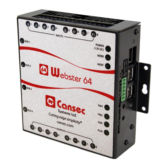
Page 7: Webster 64 Controller Layout
Webster 64 Controller Layout Figure 1 Webster 64 Page 7 of 32 Installation Manual February 2024 • Rev. 1.1... - Page 8 Important Installation Notes Controller Provisioning Options: The Webster 64 controller has two options, 2 doors and 4 doors, and can be ordered as such. Door configurations are as follow: 1. Webster 64 controller only: a. Default configuration is 2–door configuration: 2 lock relays, 2 multi-function relays, 2 REX/RTE, 2 door contacts/DPS b.
- Page 9 See Appendix section for more information. Mechanical Information: 1. The Webster 64 has 2 horizontal mounting flanges, which should be used to attach the product to a stable surface. 2. If required the Webster 64 may be mounted inside of a lockable enclosure such as the CA-SLBOX or CA-H1000ENCL if access is to be limited to the external connections.
-
Page 10: Panel Installation
The Webster 64 requires an external battery backed-up 12 VDC power supply. However, as many devices can be attached to the Webster 64 controller, it may be more cost effective to use a separate power supply (battery backed-up) just for the Webster 64 Controller and a separate power supply which can be sized to supply the amount of current that the attached high-current devices (locks) will require. -
Page 11: Entry Reader Wiring
READER LED ON = Reader Active. Two Inputs and two Outputs are used for RTE/REX, door contacts well as lock relays and multi-function relays respectively. READER LED OFF = Reader Inactive. Webster 64 Page 11 of 32 Installation Manual February 2024 • Rev. 1.1... -
Page 12: Entry And Exit Reader Wiring
Webster 64 Controller prior to attaching it to a surface. It is highly recommended that the Webster 64 be removed from the attached surface to do a change of the MSJx position. See figure 6 below. - Page 13 Non-Supervised Figure 6 Webster 64 Page 13 of 32 Installation Manual February 2024 • Rev. 1.1...
- Page 14 Supervised Figure 7 Webster 64 Page 14 of 32 Installation Manual February 2024 • Rev. 1.1...
-
Page 15: Lock Output And Multi-Function Relay Wiring
Door Operator – Handicap Cards Only: Activated on only Handicap cards (Lock Opens first). DHO or Forced Entry: Activated on either DHO or Forced Entry. Webster 64 Page 15 of 32 Installation Manual February 2024 • Rev. 1.1... - Page 16 MOV is required. Check with magnetic lock supplier. See Note 2 in Appendix section for 6 Amp relay rating Figure 9 Webster 64 Page 16 of 32 Installation Manual February 2024 • Rev. 1.1...
-
Page 17: Appendix
3.63” x 5.88” x 2.5” Backup Battery 12 VDC 7 PA-SLP003 Amp Hour. Provides hours of (92.20mm x 149.35mm backup power for above power x 63.50mm) supplies. 5.00 lbs (2.27 kg) Webster 64 Page 17 of 32 Installation Manual February 2024 • Rev. 1.1... -
Page 18: Webster 64 System Indicators
MEBR LED, MEBT LED: For future use. Webster Mode: Mode indicator: Webster 64 emits 2 beeps after powered up. PM1 LED: ON, PM2 LED: OFF IOM LED: Flashing RED – IOM (Input Output Module) is in normal operation. -
Page 19: Power Connector
METBA and METBB are for future use. The Shield from METBA and METBB wire would be connected to METTAM. TAMPER allows for the connection of an external Enclosure Tamper Switch. Note: The Webster 64 has a Tamper MSJx–MicroShunt jumper to the right of this power connector. Figure 14... -
Page 20: Pb1 - Shutdown Button
GND – this is the 12 volt power supply ground. 12VDC IN – Power for Webster 64. 12 volt DC battery backed up power supply. This is the power for the Webster 64 and readers attached. PB1 – SHUTDOWN BUTTON As the Webster 64 contains a mini computer, a proper system shutdown is nesscessary to prevent data corruption. - Page 21 DHCP enabled. Existing database will not be reset or erased. Note: The end of the reboot cycle is indicated by a Webster 64 turning back on the associated system LEDs and at the end it will emit 3 beeps.
- Page 22 Note: The optional Trusted Host IP (see Figure 18) instructs the panel to accept data connection only from the host computer accessing the controller’s port 5000. Leave it unchecked for Webster to function properly. Figure 18 Webster 64 Page 22 of 32 Installation Manual February 2024 • Rev. 1.1...
-
Page 23: Usb Ip Configuration Tool
Important: Shutdown Push Button (PB1) must be used to avoid data corruption on the Webster 64 controller. 1. If the Webster 64 controller is powered on, press and hold the PB1 button for a period of 5 to 8 seconds and proceed to step 2. Otherwise, proceed to step 4. - Page 24 3. Wait until the Webster 64 does a complete shutdown, indicated by all Webster 64 LEDs going to the OFF state (except the Power LED), and unplug the power connector. 4. Insert a FAT32 formatted USB flash drive into an available USB connector on the Webster 64 controller.
- Page 25 ClientIp 0.0.0.0 If IpSecurity is enabled and ClientIp has a valid IP address specified then the Webster 64 controller accepts data connection (SrvPort 5000) from only this host computer. Other connections on DiagPort 5001 and UpdatePort 5002 are not affected by this setting.
- Page 26 13. If no error file is present, it’s recommended that the file MAPCFG.txt be reviewed to ensure that the line <USB INIT DONE> has been written by the Webster 64 controller indicating that the IP configuration has been successfully saved and initialized. Webster 64...
-
Page 27: Default Factory Static Ip Configuration
3. After approximately 3-5 seconds the Webster 64 controller will emit a continuous beep. Release the IP RESET PB2 button. 4. The Webster 64 controller will be reset and reboot with a default factory static IP address of 10.0.0.101. 5. Insert the tamper jumper, TAMPER = SHORTED. Note: If this is not done, on the next IP reset the controller will always return to the default factory static IP address of 10.0.0.101. - Page 28 9. Right click on your network adapter, in this example it’s Ethernet 2, and select Properties. 10. Select Internet Protocol Version 4 (TCP/IPv4) and select Properties button. Webster 64 Page 28 of 32 Installation Manual February 2024 • Rev. 1.1...
- Page 29 10.0.0.200 followed by the Subnet mask of 255.255.255.0. When done select OK all the way out. 12. Your network card is now configured with an alternative IP address of 10.0.0.200 which is in the same subnet of the Webster 64 controller 10.0.0.101. Webster 64 Page 29 of 32 Installation Manual February 2024 •...
-
Page 30: Forced Entry Output
, will be activated if the door is forced open without either an access-granted or an exit-button event. A message will be recorded and displayed in Webster 64 transaction log. DOOR HELD OPEN OUTPUT Door Held Open... -
Page 31: Alarm Shunt Output
Door Held Open Forced Entry activated on either event or event. A message will be recorded and displayed in Webster 64 transaction log. © Cansec Systems Ltd., 2023 All rights reserved Webster 64 Page 31 of 32 Installation Manual February 2024 • Rev. 1.1... - Page 32 Webster 64 Page 32 of 32 Installation Manual February 2024 • Rev. 1.1...
Need help?
Do you have a question about the Webster 64 and is the answer not in the manual?
Questions and answers