Table of Contents
Advertisement
Quick Links
Advertisement
Table of Contents

Related Manuals for HIKVISION DS-KB8113-IME1(B) Series


Summary of Contents for HIKVISION DS-KB8113-IME1(B) Series
- Page 1 DS-KB8113-IME1(B) Series Vandal-Resistant Door Saon User Manual...
- Page 2 WITHOUT LIMITATION, MERCHANTABILITY, SATISFACTORY QUALITY, OR FITNESS FOR A PARTICULAR PURPOSE. THE USE OF THE PRODUCT BY YOU IS AT YOUR OWN RISK. IN NO EVENT WILL HIKVISION BE LIABLE TO YOU FOR ANY SPECIAL, CONSEQUENTIAL, INCIDENTAL, OR INDIRECT DAMAGES,...
- Page 3 During the use of device, personal data will be collected, stored and processed. To protect data, the development of Hikvision devices incorporates privacy by design principles. For example, for device with facial recognion features, biometrics data is stored in your device with encrypon method;...
- Page 4 DS-KB8113-IME1(B) Series Vandal-Resistant Door Saon User Manual Symbol Convenons The symbols that may be found in this document are dened as follows. Symbol Descripon Indicates a hazardous siuaon which, if not avoided, will or could Danger result in death or serious injury.
- Page 5 DS-KB8113-IME1(B) Series Vandal-Resistant Door Saon User Manual Safety Insrucon Warning All the electronic operaon should be strictly compliance with the electrical safety regulaons, ● re prevenon regulaons and other related regulaons in your local region. Please use the power adapter, which is provided by normal company. The power consumpon ●...
- Page 6 DS-KB8113-IME1(B) Series Vandal-Resistant Door Saon User Manual Improper use or replacement of the baery may result in hazard of explosion. Replace with the ● same or equivalent type only. Dispose of used baeries according to the insrucons provided by the baery manufacturer.
- Page 7 DS-KB8113-IME1(B) Series Vandal-Resistant Door Saon User Manual Regulatory Inormaon FCC Inormaon Please take aenon that changes or modicaon not expressly approved by the party responsible for compliance could void the user's authority to operate the equipment. FCC compliance: This equipment has been tested and found to comply with the limits for a Class B digital device, pursuant to part 15 of the FCC Rules.
- Page 8 DS-KB8113-IME1(B) Series Vandal-Resistant Door Saon User Manual under the EMC Direcve 2014/30/EU, RE Direcve 2014/53/EU,the RoHS Direcve 2011/65/EU 2012/19/EU (WEEE direcve): Products marked with this symbol cannot be disposed of as unsorted municipal waste in the European Union. For proper recycling, return this product to your local supplier upon the purchase of equivalent new equipment, or dispose of it at designated collecon points.
- Page 9 DS-KB8113-IME1(B) Series Vandal-Resistant Door Saon User Manual Cet équipement doit être installé et ulisé à une distance minimale de 20 cm entre le radiateur et votre corps. viii...
-
Page 10: Table Of Contents
DS-KB8113-IME1(B) Series Vandal-Resistant Door Saon User Manual Contents Chapter 1 Appearance ........................ 1 Chapter 2 Terminal and Wiring Descripon ................. 3 2.1 Terminal Descripon ......................3 2.2 Wiring Descripon ......................... 4 2.2.1 Door Lock Wiring ......................4 2.2.2 Door Contact Wiring ..................... 5 2.2.3 Exit Buon Wiring ...................... - Page 11 DS-KB8113-IME1(B) Series Vandal-Resistant Door Saon User Manual 7.4.3 Network Setngs ......................27 7.4.4 Video & Audio Setngs ....................31 7.4.5 Image Setngs ......................35 7.4.6 Event Setngs ......................38 7.4.7 Intercom Setngs ......................42 7.4.8 Access Control Setngs ....................45 Appendix A.
-
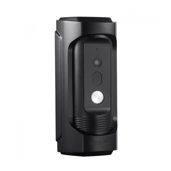
Page 12: Chapter 1 Appearance
DS-KB8113-IME1(B) Series Vandal-Resistant Door Saon User Manual Chapter 1 Appearance Figure 1-1 Appearance Table 1-1 Component Descripon Descripon Microphone Built-in Camera Low Illuminaon Supplement Light... - Page 13 DS-KB8113-IME1(B) Series Vandal-Resistant Door Saon User Manual Descripon Call Buon Loudspeaker...
-
Page 14: Chapter 2 Terminal And Wiring DescripOn
DS-KB8113-IME1(B) Series Vandal-Resistant Door Saon User Manual Chapter 2 Terminal and Wiring Descripon 2.1 Terminal Descripon Figure 2-1 Terminals Descripon Table 2-1 Descripon Name Interface Descripon Power Supply 12 VDC 12 VDC Power Supply Input Network Interface (PoE Supported) ALARM IN... -
Page 15: Wiring DescripOn
DS-KB8113-IME1(B) Series Vandal-Resistant Door Saon User Manual 2.2 Wiring Descripon 2.2.1 Door Lock Wiring Terminal NC/COM is set as default for connecng magnec lock/electric bolt; terminal NO/ COM is set as default for connecng electric strike. To connect electric lock, it is required to set the output of terminal NC/COM/NO to be electric lock via Batch Conguraon Tool or iVMS-4200 client sofware or the web browser. -
Page 16: Door Contact Wiring
DS-KB8113-IME1(B) Series Vandal-Resistant Door Saon User Manual 2.2.2 Door Contact Wiring To connect door contact, it is required to set the output of terminal AI to be door status via Batch Conguraon Tool or iVMS-4200 client sofware or the web browser. - Page 17 DS-KB8113-IME1(B) Series Vandal-Resistant Door Saon User Manual Figure 2-4 Exit Buon Wiring...
-
Page 18: Alarm Device Input Wiring
DS-KB8113-IME1(B) Series Vandal-Resistant Door Saon User Manual 2.2.4 Alarm Device Input Wiring When you set the output of terminal AI to be custom via Batch Conguraon Tool or iVMS-4200 client sofware or the web browser, you can connect any alarm input device to the door saon via the terminal AI. -
Page 19: Chapter 3 Door SAOn InsAllaOn
DS-KB8113-IME1(B) Series Vandal-Resistant Door Saon User Manual Chapter 3 Door Saon Insallaon 3.1 Wall Mounng Plate To install the door saon onto the wall, you are required to use a matched mounng plate. Figure 3-1 Wall Mounng Plate 3.2 Wall Mounng Steps 1. - Page 20 DS-KB8113-IME1(B) Series Vandal-Resistant Door Saon User Manual Figure 3-2 Install the Plate 2. Insert terminal blocks into the interfaces of the door saon body, and connect the network cable.
- Page 21 DS-KB8113-IME1(B) Series Vandal-Resistant Door Saon User Manual Figure 3-3 Insert Terminals and Network Cable 3. Fix the door saon body to the proecve shield ghly.
- Page 22 DS-KB8113-IME1(B) Series Vandal-Resistant Door Saon User Manual Figure 3-4 Fix the Body to the Shield 4. Hook the door saon to the wall mounng plate ghly.
- Page 23 DS-KB8113-IME1(B) Series Vandal-Resistant Door Saon User Manual Figure 3-5 Hook the Door Saon to the Plate 5. Use the set screw to secure the door saon with the mounng plate.
- Page 24 DS-KB8113-IME1(B) Series Vandal-Resistant Door Saon User Manual Figure 3-6 Secure the Door Saon...
-
Page 25: Chapter 4 AcVaE Device Via Web
DS-KB8113-IME1(B) Series Vandal-Resistant Door Saon User Manual Chapter 4 Acvae Device via Web You are required to acvae the device rs by setng a strong password for it before you can use the device. Default parameters of the door saon are as follows: Default IP Address: 192.0.0.65. -
Page 26: Chapter 5 Remote ConGuraOn Via Indoor SAOn
DS-KB8113-IME1(B) Series Vandal-Resistant Door Saon User Manual Chapter 5 Remote Conguraon via Indoor Saon 5.1 Set Up Door Saon via Indoor Saon Steps 1. Choose Language and tap Next. 2. Set network parameters and tap Next - Edit Local IP, Subnet Mask and Gateway parameters. - Page 27 DS-KB8113-IME1(B) Series Vandal-Resistant Door Saon User Manual Note Besides the indoor saon, you can also unlock the door by the master saon, the client ● sofware, and the web. When the video intercom between you and the resident is realized, you can speak to the ●...
-
Page 28: Chapter 6 Remote ConGuraOn Via Mobile Client
DS-KB8113-IME1(B) Series Vandal-Resistant Door Saon User Manual Chapter 6 Remote Conguraon via Mobile Client 6.1 Set Up Mobile Client Before You Start Make sure your mobile device has been connected to Wi-Fi. Hik-Connect client is necessary for door saon conguraon and operaon. -
Page 29: Remote OperaOn Via Client
DS-KB8113-IME1(B) Series Vandal-Resistant Door Saon User Manual 6.3 Remote Operaon via Client You can realize some certain uncons of the door saon via Hik-Connect (including, but not limited to, live view, and remote playback). Live View Tap the door saon in the list to open the oang windows. And then tap the oang window to enter the Live View page. - Page 30 DS-KB8113-IME1(B) Series Vandal-Resistant Door Saon User Manual Figure 6-1 Playback Synchronize Time On the Live View page, tap ... → Setngs , you can set the me of door saon. Tap Time Zone to select the right me zone. Tap Date Format to change the format.
- Page 31 DS-KB8113-IME1(B) Series Vandal-Resistant Door Saon User Manual Alarm Nocaon On the Live View page, tap ... → Setngs → Nocaon , slide the slider to enable alarm nocaon. Tap Draw Moon Deecon Area and select area. Tap to save. Figure 6-2 Draw Moon Deecon Area Tap Moon Deecon Sensiviy to adjust the sensiviy.
- Page 32 DS-KB8113-IME1(B) Series Vandal-Resistant Door Saon User Manual Note The messages will be pushed auomacally by enabling Receive Events and Push Nocaons. ● The client can receive the triggered alarm auomacally when the door saon is powered on by ● Receive Events but NOT Push Nocaons.
-
Page 33: Chapter 7 Remote ConGuraOn Via Web
DS-KB8113-IME1(B) Series Vandal-Resistant Door Saon User Manual Chapter 7 Remote Conguraon via Web 7.1 Live View In the browser address bar, enter the IP address of the device, and press the Enter key to enter the login page. Enter the user name and password and click Login to enter the Live View page. Or you can click Live View to enter the page. -
Page 34: Device Management
DS-KB8113-IME1(B) Series Vandal-Resistant Door Saon User Manual Basic Inormaon Click Add to add users. Enter the Employee ID, Name, Floor No. and Room No., Set the ● Start Time and End Time. You can set the user as Administrator. Note If you disable Always Valid, setng start me and end me is necessary. -
Page 35: ConGuraOn
DS-KB8113-IME1(B) Series Vandal-Resistant Door Saon User Manual 7.4 Conguraon 7.4.1 Local Parameters Setngs You can congure the parameters of the live view, record les and captured pictures. The record les and captured pictures are the ones you record and capture by using the web browser. You can also set and view the saving paths of the captured pictures and recorded videos on the PC that running the web browser. -
Page 36: System Setngs
DS-KB8113-IME1(B) Series Vandal-Resistant Door Saon User Manual Select the image format for picture capture. Click Save to enable the setngs. Record File Parameters Record File Size Select the packed size of the manually recorded and downloaded video les to 256M, 512M or 1G. - Page 37 DS-KB8113-IME1(B) Series Vandal-Resistant Door Saon User Manual Click System Setngs → DST to check Enable DST. Set the parameters according to your needs and click Save to enable the setngs. About Click System Setngs → About and click Open Source Sofware Licenses to view the details.
-
Page 38: Network Setngs
DS-KB8113-IME1(B) Series Vandal-Resistant Door Saon User Manual Note We highly recommend you to create a strong password of your own choosing (using a minimum of 8 characters, including at least three kinds of following categories: upper case leers, lower case leers, numbers, and special characters) in order to increase the security of your product. - Page 39 DS-KB8113-IME1(B) Series Vandal-Resistant Door Saon User Manual Figure 7-3 Port Setngs 2. Set the ports of the device. HTTP Port The default port number is 80, and it can be changed to any port No. which is not occupied. RTSP Port The default port number is 554.
- Page 40 DS-KB8113-IME1(B) Series Vandal-Resistant Door Saon User Manual Figure 7-4 SIP Setngs 2. Check Enable VOIP Gateway. 3. Congure the SIP parameters. 4. Click Save to enable the setngs. FTP Setngs Steps 1. Click Network → Advanced → FTP to enter the setngs page.
- Page 41 DS-KB8113-IME1(B) Series Vandal-Resistant Door Saon User Manual Figure 7-5 FTP Setngs...
-
Page 42: Video & Audio Setngs
DS-KB8113-IME1(B) Series Vandal-Resistant Door Saon User Manual 2. Check Enable FTP. 3. Select Server Type. 4. Input the Server IP Address and Port. 5. Congure the FTP Setngs, and the user name and password are required for the server login. - Page 43 DS-KB8113-IME1(B) Series Vandal-Resistant Door Saon User Manual Figure 7-6 Video Parameters 2. Select the Stream Type. 3. Congure the video parameters. Stream Type Select the stream type to main stream or sub stream. Video Type The video type is set as Video&Audio by default.
- Page 44 DS-KB8113-IME1(B) Series Vandal-Resistant Door Saon User Manual Frame Rate Set the frame rate. The frame rate is to describe the frequency at which the video stream is updated and it is measured by frames per second (fps). A higher frame rate is advantageous when there is movement in the video stream, as it maintains image quality throughout.
- Page 45 DS-KB8113-IME1(B) Series Vandal-Resistant Door Saon User Manual Figure 7-7 Audio Setngs 2. Congure the stream type and the audio encoding type. Audio Channel Select the audio channel to adjust the audio parameters. Stream Type Select the stream type to main stream or sub stream.
-
Page 46: Image Setngs
DS-KB8113-IME1(B) Series Vandal-Resistant Door Saon User Manual 7.4.5 Image Setngs Display Setngs Congure the image adjustment, backlight setngs and other parameters in display setngs. Steps 1. Click Image → Display Setngs to enter the display setngs page. Figure 7-8 Display Setngs 2. - Page 47 DS-KB8113-IME1(B) Series Vandal-Resistant Door Saon User Manual Sharpness Sharpness describes the edge contrast of the image, which ranges from 1 to 100. 5. Set the Day/Night Switch. Figure 7-9 Day/Night Switch - Set Dayme or Night. - Set the mode as Auto and edit the sensiviy according to your needs.
- Page 48 DS-KB8113-IME1(B) Series Vandal-Resistant Door Saon User Manual OSD Setngs You can customize the camera name, me/dae format on the live view. Steps 1. Click Image → OSD to enter the setngs page. Figure 7-11 OSD 2. Check to enable Display Name, Display Date or Display Week at your actual needs.
-
Page 49: Event Setngs
DS-KB8113-IME1(B) Series Vandal-Resistant Door Saon User Manual Note You can select Cropping Resoluon as 704*576, 1280*720, or 1920*1080. ● You can zoom in or zoom out the image by selecng Cropping Resoluon afer clicking Save. ● 7.4.6 Event Setngs Moon Deecon Moon deecon detects the moving objects in the congured security area, and a series of... - Page 50 DS-KB8113-IME1(B) Series Vandal-Resistant Door Saon User Manual Figure 7-12 Moon Deecon 2. Click to Enable Moon Deecon. 3. Click Draw Area. Click and drag to draw a moon deecon area. Clear Area Click Clear All to clear all of the areas.
- Page 51 DS-KB8113-IME1(B) Series Vandal-Resistant Door Saon User Manual Delete Schedule Click Delete to delete the current arming schedule. 6. Click Linkage Method to enable the linkages. Noy Security Center Send an excepon or alarm signal to the remote management sofware when an event occurs.
- Page 52 DS-KB8113-IME1(B) Series Vandal-Resistant Door Saon User Manual Figure 7-13 Event Linkage...
-
Page 53: Intercom Setngs
DS-KB8113-IME1(B) Series Vandal-Resistant Door Saon User Manual 2. Select the Major Type as Device Event or Door Event. 3. Select the Minor Type. - For device event, the Minor Type is set as Tampering Alaem by default. - For door event, select Minor Type as Door Open Timed Out (Door Contact). - Page 54 DS-KB8113-IME1(B) Series Vandal-Resistant Door Saon User Manual Figure 7-14 Session Setngs 2. Set Regisraon Password. 3. Set Main Saon IP and Private Server IP. 4. Slide to enable Protocol 1.0. 5. Click Save to enable the setngs. Call Setngs Go to Intercom → Call Setngs to enter the page.
- Page 55 DS-KB8113-IME1(B) Series Vandal-Resistant Door Saon User Manual Press Buon to Call Steps 1. Click Intercom → Press Buon to Call to enter the setng page. 2. Check Call Management Centeror Call Specied Indoor Saon to set the buon. Note If you check Call Specied Indoor Saon, you should enter the specied indoor saon No.
-
Page 56: Access Control Setngs
DS-KB8113-IME1(B) Series Vandal-Resistant Door Saon User Manual Figure 7-15 Number Setngs Click Add, set the Room No. and SIP numbers in the pop-up dialog box. 7.4.8 Access Control Setngs Door Parameters Set the parameters of the door which is linked to the device. - Page 57 DS-KB8113-IME1(B) Series Vandal-Resistant Door Saon User Manual Figure 7-16 Door Parameters 2. Select Door No., and edit the Name. 3. Set Open Duraon. When the me to open over the open duraon you set, the door will be locked again.
-
Page 58: Appendix A. Appendix
DS-KB8113-IME1(B) Series Vandal-Resistant Door Saon User Manual Appendix A. Appendix Insallaon Noce While installing the door saon, make sure that the distance between any two devices is far enough to avoid the howling and echo. The distance between two devices is recommended to be longer than 10 meters. -
Page 59: Appendix B. CommunicaOn Matrix And Device Command
Device Command Scan the following QR code to get the device common serial port commands. Note that the command list contains all commonly used serial ports commands for all Hikvision access control and video intercom devices. Figure B-2 Device Command... - Page 60 UD31659B...
Need help?
Do you have a question about the DS-KB8113-IME1(B) Series and is the answer not in the manual?
Questions and answers