
Subscribe to Our Youtube Channel
Related Manuals for Applied Comfort COOLFLOW32


Summary of Contents for Applied Comfort COOLFLOW32
- Page 1 COOLFLOW32 USER MANUAL TPHE10G10EG 230V,60HZ WITH ELECTRIC HEAT WALL MOUNTED TWIN PIPE AIR CONDITIONER WITH HEAT PUMP AND WIFI SMART APP...
-
Page 2: Table Of Contents
CONTENTS SAFETY AND INSTRUCTIONS PRODUCT OVERVIEW PRODUCT DIAGRAM FEAT URES WHAT’S INCLUDED INSTALLATION TOOLS REQUIRED INSTALLATION O P E RAT IO N CONTROL PANEL REMOTE CONTROL FUNCTIONS WIFI SETUP AND SMART FEATURES S E T U P REGISTER THE APP CONNECTING USING BLUETOOTH &... -
Page 3: Safety And Instructions
Safety and Instructions READ ALL INSTRUCTIONS BEFORE USE. Your safety and the safety of others is very important. We have provided many important safety messages in this manual and on your appliance. Always read and follow all safety messages. This symbol shows that this appliance uses a flammable refrigerant. If the refrigerant is leaked and exposed to an external ignition source, there ... - Page 4 WARNING To reduce the risk of explosion, fire, death, electric shock, scalding or injury to persons when using this product, follow basic precautions, including the following: INSTALLATION ●Before use, the appliance must be properly installed as described in this manual. ●Contact the authorized service technician for repair or maintenance of this unit.
- Page 5 ●Do not place the power cord near a heat source. ●Do not use an adaptor or plug the product into a shared outlet. ●Do not tamper with controls. ●If you detect a strange sound, a chemical or burning smell, or smoke coming from the appliance, unplug it immediately, and contact dealer.
- Page 6 REFRIGERANT (FOR R32 ONLY) CAUTION: FIRE READING THE MAUAL CAREFULLY BEFORE USING THE APPLIANCE R32 refrigerant gas complies with international environmental directives. This appliance contains approximately 19.40 Oz refrigerant gas. Warnings Do not use means to accelerate the defrosting process or to clean, other than those recommended by the manufacturer.
- Page 7 When using the product, the room should keep any required ventilation openings clear of obstruction. Notice that servicing shall be performed only as recommended by the manufacturer. Unventilated area ●That an unventilated area where the appliance using flammable refrigerants is installed shall be so constructed that should any refrigerant leak, it will not stagnate so as to create a fire or explosion hazard.
-
Page 8: Product Overview
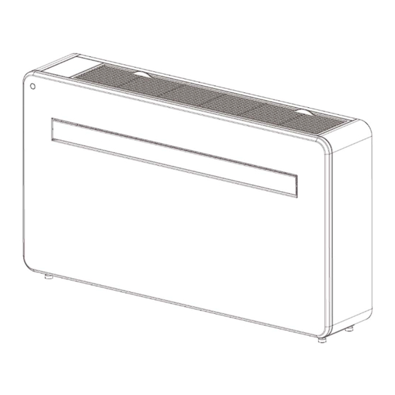
PRODUCT OVERVIEW PRODUCT DIAGRAM FRONT AIR INLET CONTROL PANEL LOUVER FRONT PANEL BACK WALL HANGING MOUNTS BACK PANEL AIR INLET AIR OUTLET DRAINAGE PIPE ... -
Page 9: Features
FEATURES Simple operation. Self-evaporative function with energy saving technology. Sleek design that seamlessly fits into any style home. Bright LED screen-indicates temperature and current mode. On / off timer function-allows you to choose when the unit operates. ... -
Page 10: Installation
INSTALLATION Apply the sealing strip in the accessories along the edge of the back for the whole perimeter of the machine, cut off the excessive length if needed. Note:1.The sealing strip should be applied along the edge of the machine, as shown in Figure1. 2. Please peel the striping layer on the sealing strip gradually while applying. Apply from the bottom of the machine first. The position of the corner should be applied as shown in Figure 2. Improper application may cause extra noise. -
Page 11: Tools Required
TOOLS REQUIRED SPIRIT LEVEL TAPE MEASURE PENCIL SHARP KNIFE 180mm CORE DRILL 8mm(5/16")MASONRY 25mm(1")MASONRY DRILL BEFORE STARTING INSTALLATION, PLEASE ENSURE YOU HAVE ALL SUITABLE EQUIPMENT AVAILABLE AND UNDERSTAND THE STEPS INVOLVED IN INSTALLATION. IF IN ANY DOUBT, PROFESSIONAL ADVICE SHOULD BE SOUGHT. THE INSTALLER MUST ENSURE THAT THE PLANNED POSITION OF THE AIR CONDITIONER IS SUITABLE, AND THAT THERE ARE NO CABLES AND PIPES INSIDE THE WALL, AND NO OTHER OBSTRUCTIONS FIXED ON THE WALL, WHICH WOULD PRESENT A DANGER AND/OR PREVENT COMPLETION OF INSTALLATION. INSTALLATION This unit must be installed on an external wall, as it vents directly out of its rear.and ensure the wall is flat, solid and reliable. Leave at least 10 cm (4 ") of space to the left, right and base of the machine. At least 20cm (8 ") of space must be left above the unit to help air flow smoothly and stay away from curtains, plants, faucets, furniture and others appliances etc. Paste the supplied installation template paper in position on the wall, ensuring that the reference line is level using a spirit level. ... - Page 12 The hole for the drainage pipe must be drilled using a 25mm (1 ") Drill bit. Ensure the hole is at a downward angle (min 5 degrees) so that the water will drain correctly. Use a 180mm core drill to drill the two holes for the units’ Ventilation ducts, ensuring that the holes are at a downward angle toward the outdoors (min 5 degrees) and aligned with the template. Use the template to mark the position of the screws for the hanging rail, using a spirit level to ensure it is straight and level. Drill the marked holes using a suitable 8mm(5/16") drill bit and insert wall plugs. Line up the hanging rail with the holes, and fix the rail into position using the supplied screws. Ensure that the hanging rail is securely fastened onto the wall, and that there is no risk of the unit tipping or falling. The machine performs best when it is installed on a wall with a thickness not exceeding 240mm. Roll the plastic vent sheets into a tube and feed them from the inside into the holes previously made. Ensure the tubes sit flush to the interior wall and the splicing line “A” always faces upwards. Trim off the excess vent tube using a sharp knife, keeping the edge as neat as possible. ...
- Page 13 Insert the indoor fixing ring from the vent cover onto the indoor side of the air vent. Then fold the external vent cover in half. Attach the chains to each side of the vent cover, before sliding the cover outside through the vent hole. Expand the external cover, before tightly fixing the chains by hooking onto the indoor fixing ring. This will hold the external cover firmly in position. Repeat for the second vent. Once the chains are fitted and secured, any excess chain should be removed by cutting the chain. Lift the unit onto the wall, align the hanging holes with the hooks on the hanging rail and gently rest the unit into place. At the same time, slide the drain pipe through the drainage hole. ...
- Page 14 NOTE: : please ensure that the backside of product is tightly attached on the wall to avoid additional vibration and noise. : The end of the external water pipe must be placed in an open space or drain. Avoid damage or constriction to the drainage pipe to ensure the unit drains.
-
Page 15: Operation
OPERATION CONTROL PANEL REMOTE CONTROL The air conditioner can be controlled with the remote control. Two AAA-batteries are required. NOTE: Further details of the functions can be found on the following page. POWER Press the POWER button to turn the machine on or off. Press the MODE button to switch between cooling, heating, MODE fan and dry modes. Press the FAN button to change between high, medium and low fan speeds ... - Page 16 INSERTING AND REPLACING BATTERIES Your air conditioning unit comes with two AAA batteries. Put the batteries in the remote control before use. 1.Remove the cover on the back of the remote control. 2.Insert the new batteries and make sure that the (+) and (‐) terminals of the batteries are installed correctly. BATTERY NOTES For optimum product performance: 1.Do not mix old and new batteries, or batteries of different types. 2.Do not leave batteries in the remote control if you don’t plan on using the device for more than 2 months. BATTERY DISPOSAL Do not dispose of batteries as unsorted municipal waste. Refer to local laws for proper disposal of batteries. TIPS FOR USING REMOTE CONTROL The remote control must be used within 8 meters / 26 feet of the unit. The unit will beep when remote signal is received. Curtains, other materials and direct sunlight can interfere with the infrared signal receiver. Remove batteries if the remote will not be used more than 2 months. NOTES ● When there are wide differences between remote controller Illustration and “USER’S MANUAL” on function description, the description on “USER’S MANUAL” shall prevail.
-
Page 17: Functions
● Increase the separation between the equipment and receiver. ● Connect the equipment into an outlet on a circuit different from that to which the receiver is connected. ● Consult the dealer or an experienced radio/TV technician for help. Changes or modifications not approved by the party responsible for compliance could void user’s authority to operate the equipment. FUNCTIONS Press “POWER” to turn the unit On or Off. POWER Press to change between the 4 different modes. The display will show the symbol for the mode currently selected. The cooling function allows the air conditioner to cool the room and at the same time reduces air humidity. The desired temperature can be adjusted using the increase and ℉/15℃ ℉/30℃ decrease button between 60 and 86 . The fan speed can also be adjusted COOLING using the speed button. Dry mode will extract moisture from the air, which will be drained outside using the installed drain pipe. the fan speed cannot be adjusted in dry mode. DRY MODE In fan mode the appliance will recirculate the air within the room, and will not cool, heat or dehumidify. The fan speed can be adjusted using the Speed button, But the desired FAN ... - Page 18 ℉/15℃-30℃ Used within cooling and heating modes to adjust the desired temperature 60‐86 . Also used while setting the timer to adjust the duration. INCREASE AND DECREASE After machine turns on, press the “SWING” button, louver will swing continuously up and down; by SWING pressing the button again the movement will stop and the louver remain in that position. Swing mode MODE can only be adjusted from the remote, and will initially be turned on by default. The louver will close automatically once you switch OFF the product. COMPRESSOR There is a 3 minutes delay on power on. In order to protect the life of the compressor and electronic components please do not switch on the unit for at least 5 minutes after you turned the unit off. PROTECTION The unit has an additional PTC electric heating element. When the weather conditions outside are cold, you can press the PTC button on the remote control to turn on the electric heating function to PTC electric increase the heat. The heat power of the PTC is equal to 1000W. heating function PTC turn on Only in the heating mode, press the PTC button on the remote control to send the turn‐on command to the unit. At this time, the remote control and the unit display lights up at the same time. After the unit receives the remote control command, the system will carry out self‐testing, PTC will work when the following points are satisfied at the same time. Otherwise, PTC cannot work.: a. Unit is in heating mode. b. Tw<25℃/77℉ (outdoor temperature keeps lower than 25℃/77℉ for 10 seconds ) c.
-
Page 19: Wifi Setup And Smart Features
PTC turn off Presses the PTC button again or change to other mode to turn off PTC function, the lights on remote control and the unit display will be off at the same time. NOTE: The unit will work without PTC function as a default until the “PTC” button on remote control is pressed. If unit is turned off, the PTC setting will be cleared, and it needs to be set again. WIFI SETUP AND SMART FEATURES WIFI SETUP BEFORE YOU START Ensure your router provides a standard 2.4ghz connection. If your router is dual band ensure that both networks have different network names (SSID). The provider ... -
Page 20: Register The App
REGISTER THE APP If you don't have an App account , register an account or sign in with verification code by SMS. This page describes the registration process. Press on the “Sign Up” button at the bottom of the screen, as shown in the picture 1. The system automatically recognizes your country/ area. -
Page 21: Connecting Using Bluetooth & Wifi
CONNECTING USING BLUETOOTH & WIFI Before initiating the connection, make sure the unit is in standby mode and connected to the wifi network. Open the Bluetooth of your phone , as shown in the picture 4. 2. When the device is powered on and to be connected, the connected Bluetooth device will pop up automatically after opening the App for a moment. Click "Add" button for connection, as shown in the picture 5. Enter the Wi‐Fi information interface, enter the password and click "Next" to continue the operation, as shown in the picture 6. Picture 4 Picture 5 Picture 6 and the device is successfully 4. Enter the device connection interface after the progress bar is finished connected, as shown in the picture 7,8,9. - Page 22 Picture 7 Picture 8 Picture 9 If you don’t want to use Bluetooth connection, just need to Exit the Bluetooth connection prompt or turn off Bluetooth and follow the below steps to connect the unit with Wifi connection. 1. Click "Add Device" for operation, as shown in the picture 10. Select the type of device as “Large Home Appliance”, as shown in the picture 11. , Connect a WIFI and enter the password. as shown in the picture 12.
- Page 23 Picture 10 Picture 11 Picture 12 4. Ensure the WIFI light on the air conditioner is flashing twice per second, as shown in the picture 13. Enter the device connection interface after the progress bar is finished and the device is successfully connected. Click the "Done" button to enter the operation interface of the device, as shown in the picture 14,15 Picture 13 Picture 14 Picture 15 ...
-
Page 24: Troubleshooting
*Due to continuous development of the app, the layout and available features may be subject to change. TROUBLESHOOTING Do not repair or disassemble the air conditioning. Unqualified repair will invalidate the warranty and may lead to failure, causing injuries and property damage. Only use it as directed in this user manual and only perform operations advised here. Problem Reasons Solutions Check the unit is plugged in, and the socket There is no electricity. is working normally. Only use to use the machine with a room The ambient temperature is too low or ℉/-5 ℉ ℃ and 95 temperature between 23 too high. ℃ . The air conditioner does In cooling mode, the room temperature not work is lower than the desired temperature; Adjust the desired room temperature. in heating mode, the room temperature is higher than the desired temperature. Ensure that the room temperature is above In dehumidification (dry) mode, the ℉/17 ℃... -
Page 25: Error Codes
ERROR CODES Fault Fault Fault Description Fault Description Code Code F1 Compressor IPM error Defrost protection on coil tube(indoor) F2 PFC/IPM error Zero‐crossing fault detection(indoor) F3 Compressor start error Return air sensor temperature abnormal protection F4 Compressor running out of step PC Coil tube overload protection(outdoor) F5 Location detection loop failure Abnormal refrigerant circulation F6 PCB and driver board communication error PH Exhaust temperature protection F7 Coil sensor error(outdoor) E0 Sensor on suction pipe error F8 Sensor on suction pipe error Temperature sensor error(indoor) FA Phase current overcurrent protection E2 Sensor error on indoor coil tube FE EE error(outdoor) ...
Need help?
Do you have a question about the COOLFLOW32 and is the answer not in the manual?
Questions and answers