
Related Manuals for Applied Comfort VF20HA09K36E7M90


Summary of Contents for Applied Comfort VF20HA09K36E7M90
- Page 1 MODELS SERIES VF20HA09K36E7M90 VF20HA12K36E7M90 VF20HA18K50E8M80 ATTENTION INSTALLATION PROFESSIONAL...
- Page 2 RECOGNIZE THIS SYMBOL AS A SAFETY PRECAUTION WARNING The manufacturer will not be responsible for any injury or property, damage arising from improper service or service procedures. If you install or perform service on this unit, you assume responsibility for any personal injury or property damage which may result.
-
Page 3: On/Off Switches
OPERATION INSTRUCTION Controls-terminal connections ON/OFF switches Switch side shipping screws side shipping screws terminals are still HOT and must not be touched. servicing. R FD GH B Y W GL C Red-24VAC Front Desk Control Green-High fan speed Blue-Reversing valve Yellow-Compressor White-Heater Orange... -
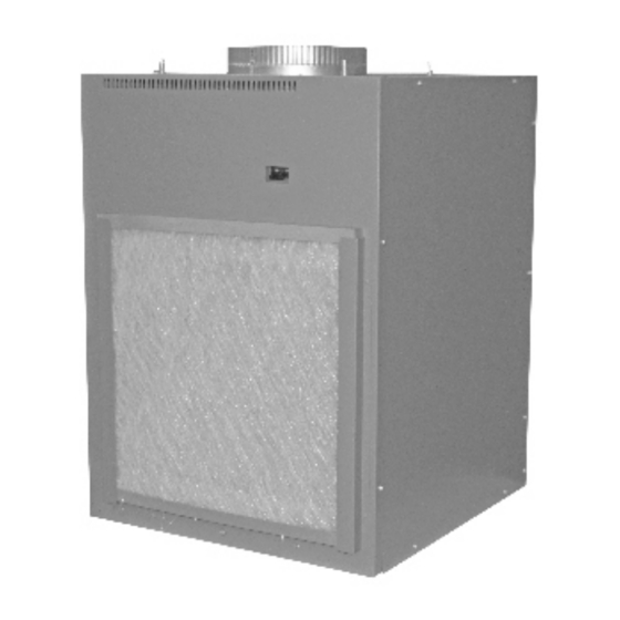
Page 4: Air Filters
Turn off the Unit and disconnect the power supply before cleaning Air Filters To maintain optimum performance, change the The coils on the unit should be checked filter at least every 30 days. The most important regularly. If they are clogged with dirt or soot, thing you can do to maintain the unit is to change they may be professionally cleaned.You will the filter at least every 30 days. -
Page 5: Installation Instruction
INSTALLATION INSTRUCTION BEFORE YOU BEGIN Read these instructions completely and carefully. RISK OF ELECTRIC SHOCK. All electrical connections and w i r i n g MUST be installed by a qualified electrician. Follow the National Electrical Code (NEC), the Canadian Electrical Code (CEC) , a n d / o r local codes and ordinances, as applicable. -
Page 6: Electrical Requirement
INSTALLATION INSTRUCTION Electrical Requirement • LCDI Cords(230/208V models only)- The power cord is located inside the electrical control box cover for insert mounting. Underwriters Laboratories and the National Electric Code (NEC) now require power cords that sense LCDI Power cord current leakage and can open the electrical circuit to the unit on units rated at 250 volts or less. -
Page 7: Required Accessories
Unit Component Case Unit Front Case Panel Required Accessories (Check the"Essential Elements"label on the unit.) Cutout Dimensions: 20" W x 32 1/4"H Wall Plenum 6"D x 19-3/4 "W x 32"H Architectural Louver 8"D x 19-3/4"W x 32"H 12"D x 19-3/4"W x 32"H 15"D x 19-3/4"W x 32"H 33"... -
Page 8: Top View
UNIT INSTALLED THROUGH SIDE OF CASE Top View Architectural Louver Architectural Louver ~2-1/4" ~2-1/4" ~1" ~1" 11-1/2" 11-1/2" 5"min. 3"min. 10" 10" 10" 10" duct duct Door/access panel 3" 3" min. min. Electrical connection Electrical connection Unit Thermostat 4" min. Unit 5"... -
Page 9: Utility Closet Connection Locations
Utility Closet Connection Locations IMPORTANT: Plan and locate plenum, wall plug, drains and thermostat carefully to avoid interference. Hard-to-reach locations will make installation and service difficult! WARNING Flex duct may be used for transitions only Use rigid duct for Supply duct is intended to distribute 90°... - Page 10 Return Air Grille Installation Options The room return air grille may be installed toward the front or either side of the unit. Improper return air arrangements will cause performance problems. There are three indoor return air grille installation options. Choose the option that best suits your installation requirements.
- Page 11 Wall Plenum And Architectural Louver Installation Since the unit itself does not install in the wall opening, the use of a plenum is necessary to contain and separate the outdoor air paths. The plenum must be able to hold water in the bottom without leaking into the wall cavity.
-
Page 12: Side View
External Drain Attach a 90° PVC elbow to the unit’s female 3/4"NPT drain connector. Use the other end of the elbow to run a 3/4 " Sch. 40 PVC pipe through the knockout holes of both the wall plenum and the architectural louver to the outside. - Page 13 (3)Ductwork Prepare the closet ductwork for later connection to the case. The total flow rate(CFM) and external static pressure (ESP) available can be estimated from the chart below. The collar on top of the case accepts standard 10"duct.Pull all duct tight. Extra duct slack can greatly increase Static pressure.
- Page 14 (6)Connect The Top Duct (5a)Install And Ground The Unit To 1. Install the duct onto the air discharge outlet. The Case Unit Installed Through Front Of Case Inside wall 1. Slide the back of the unit into the case. Push the metal duct unit all of the way into the case until it stops.
-
Page 15: Control Configuration
SERVICING NOTE: We strongly recommend that any WARNING servicing be performed by a qualified individual. For ease of service. the unit can be unit, multiple removed from the case: 1. Remove the front case panel. 2. Unplug the power cord. 3. -
Page 16: Switch Setting
Switch Setting 2、SW1 1、S1 1 2 3 4 1 2 3 4 5 6 7 8 Reserved Temperature Setting Duct selected Fan CYC. For Cooling Model select Electric memory SW1.1、SW1.2—Model select Freeze protect Heat Pump Prior SW1.3—Duct select Electric heater The duct select function allows the indoor fan to be Heat pump operated at two variable fan speeds. -
Page 17: Failure Code
Error code and solutions Failure code Nature of defect Indoor temperature sensor failure Indoor coil temperature sensor failure Outdoor coil temperature sensor failure Overheating protection/defrosting Refrigerant high pressure protection Starting delay outdoor You may notice a few minutes delay in the starting if you try to restart the unit too soon after turning it off or if you adjust the thermostat right after the compressor has shut off .This is due to... -
Page 18: Troubleshooting
TROUBLESHOOTING POSSIBLE CAUSES SOLUTIONS UNIT DOES NOT START ● Check that plug is plugged securely in wall receptacle. ● Unit may have become unplugged Note :Plug has a test/reset button on it. Make sure that the ● Fuse may have blown plug has not tripped. - Page 19 THIS PAGE INTENTIONALLY LEFT BLANK...
- Page 20 Applied Comfort Products Inc. 1210 Bal moral Road, Cambridge, Ontario, Canada, N 1T 1 AS...
Need help?
Do you have a question about the VF20HA09K36E7M90 and is the answer not in the manual?
Questions and answers