
Related Manuals for Pickering PXi 40-660A


Summary of Contents for Pickering PXi 40-660A
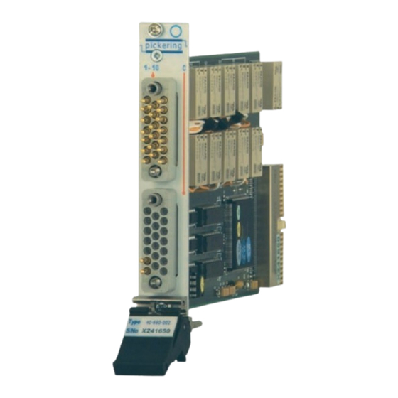
- Page 1 User Manual Power Multiplexer Module (Model No. 40-660A/665A) Issue 1.0 March 2019 pickeringtest.com pickering POWER MULTIPLEXER MODULE 40-660A / 665A Page (1)
- Page 2 © COPYRIGHT (2019) PICKERING INTERFACES. ALL RIGHTS RESERVED. No part of this publication may be reproduced, transmitted, transcribed, translated or stored in any form, or by any means without the written permission of Pickering Interfaces. Technical details contained within this publication are subject to change without notice.
- Page 3 Pickering Interfaces strives to fulfil all relevant environmental laws and regulations and reduce wastes and releases to the environment. Pickering Interfaces aims to design and operate products in a way that protects the environment and the health and safety of its employees, customers and the public. Pickering Interfaces endeavours to develop and manufacture products that can be produced, distributed, used and recycled, or disposed of, in a safe and environmentally friendly manner.
-
Page 4: Product Safety
PRODUCT SAFETY SAFETY SYMBOLS The following safety symbols may be used on the product and throughout the product documentation. MEANING / DESCRIPTION SYMBOL PROTECTIVE EARTH (GROUND) To identify any terminal which is intended for connection to an external conductor for protection against electric shock in case of a fault, or the terminal of a protective earth (ground) electrode. -
Page 5: Table Of Contents
Pre Operation Checks ............3.1 Hardware Installation ............3.2 Software Installation .............3.2 Testing Operation ..............3.3 Section 4 Programming Guide ..............4.1 Programming Options For Pickering PXI Modules ....4.1 Module Architecture 40-660A/665A ........4.2 Sub-unit Cross Reference ............4.3 Programming The Module 40-660A/665A ......4.4 Section 5 Connector Information ..............5.1 Section 6 Trouble Shooting .................6.1... - Page 6 THIS PAGE INTENTIONALLY BLANK POWER MULTIPLEXER MODULE 40-660A / 665A Page (VI)
-
Page 7: Warnings And Cautions
Not to be used in safety critical circuits, refer to the Pickering Interfaces’ terms & conditions of sale. This module must not be used for the switching of Mains Circuits. For the switching of voltages up to the module’s full specification, Secondary Circuit power supplies and the Device Under Test must... - Page 8 CAUTION - PRODUCT DOCUMENTATION SYMBOL Suitably qualified & trained users should ensure that the accompanying documentation is fully read and understood before attempting to install or operate the product. SAFETY INSTRUCTIONS SAFETY INSTRUCTIONS All cleaning and servicing requires the equipment to be isolated and disconnected from the power source and user I/O signals (refer to the Maintenance Section).
-
Page 9: Technical Specification
• VISA, IVI & Kernel Drivers Supplied for Windows • Supported by PXI or LXI Chassis • 3 Year Warranty Pickering Interfaces have a range of power switching PXI modules, available in relay, matrix or multiplexer configurations. The 40-660A is a 10-channel power multiplexer, suitable for switching inductive/capacitive loads up to 10A at 250VAC. - Page 10 SECTION 1 - TECHNICAL SPECIFICATION pickering Specifications Power Multiplexer – 40-660A/665A Relay Type The 40-660A/665A is fitted with electro-mechanical power relays, gold-flash over silver alloy. A spare relay is built onto the circuit AC Resistive board to allow easy maintenance with minimum downtime.
- Page 11 The module is compliant with the PXI Specification 2.2. Local Bus, Product Customization Trigger Bus and Star Trigger are not implemented. Pickering PXI modules are designed and manufactured on our own Uses a 33MHz 32-bit backplane interface. flexible manufacturing lines, giving complete product control and enabling simple customization to meet very specific requirements.
- Page 12 We provide a full range of supporting cable and connector solutions for all our switching products—20 connector families with 1200+ products. We offer everything from simple mating connectors to complex cables assemblies and terminal blocks. All assemblies are manufactured by Pickering and are guaranteed to mechanically and electrically mate to our modules. Connectors & Backshells...
- Page 13 Power Multiplexer – 40-660A/665A Programming Pickering provide kernel, IVI and VISA (NI & Keysight) drivers which are compatible with all Microsoft supported versions of Windows and popular older versions. For a list of all supporting operating systems, please see: pickeringtest.com/os The VISA driver is also compatible with Real-Time Operating Systems such as LabVIEW RT.
- Page 14 SECTION 1 - TECHNICAL SPECIFICATION pickering THIS PAGE INTENTIONALLY BLANK POWER MULTIPLEXER MODULE 40-660A / 665A Page 1.6...
-
Page 15: Functional Description
SECTION 2 - TECHNICAL DESCRIPTION pickering SECTION 2 - TECHNICAL DESCRIPTION FUNCTIONAL DESCRIPTION A functional block diagram is provided in Figure 2.1. The Power Multiplexer Module is powered by +12V and +5V inputs via Compact PCI connector J1. The interface to the user test equipment is via one or two front panel mounted 20-pin GMCT type connectors. - Page 16 SECTION 2 - TECHNICAL DESCRIPTION pickering THIS PAGE INTENTIONALLY BLANK POWER MULTIPLEXER MODULE 40-660A / 665A Page 2.2...
-
Page 17: Installation
Modular products require installation in a suitable PXI/LXI chassis. The module is designed for indoor use only. PREOPERATION CHECKS (UNPACKING) 1. Check the module for transport damage and report any damage immediately to Pickering Interfaces. Do not attempt to install the product if any damage is evident. -
Page 18: Hardware Installation
For a system comprising more than one chassis, turn ON the last chassis in the system followed by the penultimate, etc, and finally turn ON the external controller or chassis containing the system controller. 9. For Pickering Interfaces modular LXI installation there is no requirement to use any particular power up sequence. -
Page 19: Testing Operation
Figure 3.2 - General Soft Front Panel Icon A selector panel will appear, listing all installed Pickering PCI, PXI or LXI switch cards and resistor cards. Click on the card you wish to control, and a graphical control panel is presented allowing operation of the card. - Page 20 SECTION 3 - INSTALLATION pickering THIS PAGE INTENTIONALLY BLANK POWER MULTIPLEXER MODULE 40-660A / 665A Page 3.4...
-
Page 21: Programming Guide
SECTION 4 - PROGRAMMING GUIDE PROGRAMMING OPTIONS FOR PICKERING INTERFACES PXI MODULES For information on the installation and use of drivers and the programming of Pickering’s products in various software environments, please refer to the Software User Manual. This is available as a download from: https://www.pickeringtest.com/support/software-drivers-and-downloads... -
Page 22: Module Architecture 40-660A/665A
SECTION 4 - PROGRAMMING GUIDE pickering MODULE ARCHITECTURE 40-660A / 665A: MULTIPLEXER MODULES The 40-660A Multiplexer Module is an array of 10 SPST or DPST. The 40-665A Multiplexer Module is an array of 18 SPST relays. In the default state all relays are open circuit. Energising a particular relay creates a signal path between the common terminal(s) and the corresponding channel terminal(s). - Page 23 SECTION 4 - PROGRAMMING GUIDE pickering TABLE 4.1 - Multiplexer Module 40-660A-001: Sub-Units 40-660A-001 Sub-Unit Cross Reference Bank Channel Bank Channel com to 1 com to 6 com to 2 com to 7 com to 3 com to 8 com to 4...
-
Page 24: Programming The Module 40-660A/665A
SECTION 4 - PROGRAMMING GUIDE pickering PROGRAMMING THE MODULE 40-660A / 665A Here are some simple examples of using the drivers with the 40-660A-002 Multiplexer module. Using PILPXI To operate a relay the user could use the simple OpBit command or the WriteSub commands OpBit DWORD sub_unit = 1;... -
Page 25: Connector Information
SECTION 5 - CONNECTOR INFORMATION pickering SECTION 5 - CONNECTOR INFORMATION Figure 5.1 - 10-Channel 1-Pole Power Multiplexer Module 40-660A-001: Pinouts (20-pin male GMCT connector viewed from the front of the module) 10.1 10.2 Com1 Com2 10.1 Com 1 10.2 Com 2 Figure 5.2 - 10-Channel 2-Pole Power Multiplexer Module 40-660A-002: Pinouts... - Page 26 SECTION 5 - CONNECTOR INFORMATION pickering Figure 5.2 - 18-Channel 1-Pole Power Multiplexer Module 40-665A-001: Pinouts (20-pin male GMCT connector viewed from the front of the module) POWER MULTIPLEXER MODULE 40-660A / 665A Page 5.2...
-
Page 27: Trouble Shooting
PCI configuration, highlighting any potential configuration problems. Specific details of all installed Pickering switch cards are included. All the installed Pickering switch cards should be listed in the “Pilpxi information” section - if one or more cards is missing it may be possible to determine the reason by referring to the PCI configuration dump contained in the report, but interpretation of this information is far from straightforward, and the best course is to contact Pickering support: support@pickeringtest.com, if possible... - Page 28 SECTION 6 - TROUBLE SHOOTING pickering THIS PAGE INTENTIONALLY BLANK POWER MULTIPLEXER MODULE 40-660A / 665A Page 6.2...
-
Page 29: Maintenance Information
For PXI modules which are supported in one of Pickering Interfaces’ Modular LXI Chassis (such as the 60-102B and 60-103B) no module software update is required. If the module was introduced after the LXI chassis was manufactured the module may not be recognized, in this case the chassis firmware may need upgrading. - Page 30 SECTION 7 - MAINTENANCE INFORMATION pickering SPARE RELAY RL10 Figure 7.1 - Multiplexer Module 40-660A: Component Layout Figure 7.2 - Multiplexer Module: 40-660A POWER MULTIPLEXER MODULE 40-660A / 665A Page 7.2...
- Page 31 SECTION 7 - MAINTENANCE INFORMATION pickering Figure 7.3 - Multiplexer Module 40-665A: Component Layout Figure 7.4 - Multiplexer Module: 40-665A POWER MULTIPLEXER MODULE 40-660A / 665A Page 7.3...
- Page 32 SECTION 7 - MAINTENANCE INFORMATION pickering THIS PAGE INTENTIONALLY BLANK POWER MULTIPLEXER MODULE 40-660A / 665A Page 7.4...
Need help?
Do you have a question about the PXi 40-660A and is the answer not in the manual?
Questions and answers