
Related Manuals for Pickering PCI 50-670


Summary of Contents for Pickering PCI 50-670
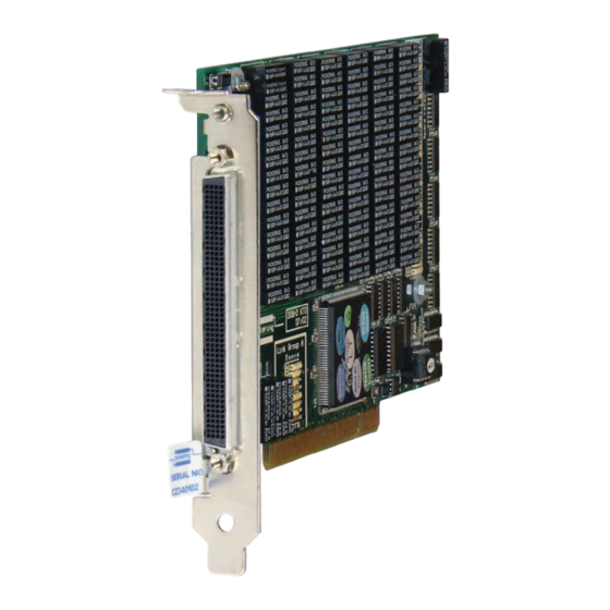
- Page 1 50-670 User Manual PCI Very High Density Multiplexer Card pickeringtest.com Issue 8.2 May 2023...
- Page 2 © COPYRIGHT (2023) PICKERING INTERFACES. ALL RIGHTS RESERVED. No part of this publication may be reproduced, transmitted, transcribed, translated or stored in any form, or by any means without the written permission of Pickering Interfaces. Technical details contained within this publication are subject to change without notice.
- Page 3 Pickering Interfaces strives to fulfil all relevant environmental laws and regulations and reduce wastes and releases to the environment. Pickering Interfaces aims to design and operate products in a way that protects the environment and the health and safety of its employees, customers and the public. Pickering Interfaces endeavours to develop and manufacture products that can be produced, distributed, used and recycled, or disposed of, in a safe and environmentally friendly manner.
-
Page 4: Product Safety
PRODUCT SAFETY SAFETY SYMBOLS The following safety symbols may be used on the product and throughout the product documentation. MEANING / DESCRIPTION SYMBOL PROTECTIVE EARTH (GROUND) To identify any terminal which is intended for connection to an external conductor for protection against electric shock in case of a fault, or the terminal of a protective earth (ground) electrode. -
Page 5: Table Of Contents
Pre Operation Checks ............3.1 Hardware Installation ............3.2 Software Installation .............3.2 Testing Operation ..............3.3 Section 4 Programming Guide ..............4.1 Programming Options For Pickering PCI Cards ....4.1 Card Architecture ..............4.2 Card Sub-Units ..............4.3 Programming The Card ............4.15 Section 5 Connector Information ..............5.1 Section 6 Trouble Shooting .................6.1... - Page 6 THIS PAGE INTENTIONALLY BLANK VERY HIGH DENSITY MULTIPLEXER CARD 50-670 Page (VI)
-
Page 7: Warnings And Cautions
Not to be used in safety critical circuits, refer to the Pickering Interfaces’ terms & conditions of sale. This card must not be used for the switching of Mains Circuits. For the switching of voltages up to the card’s full specification, Secondary Circuit power supplies and the Device Under Test must be... - Page 8 CAUTION - PRODUCT DOCUMENTATION SYMBOL Suitably qualified & trained users should ensure that the accompanying documentation is fully read and understood before attempting to install or operate the product. SAFETY INSTRUCTIONS SAFETY INSTRUCTIONS All cleaning and servicing requires the equipment to be isolated and disconnected from the power source and user I/O signals (refer to the Maintenance Section).
-
Page 9: Technical Specification
This product is based on the obsolete Molex LFH series 1 Bank, 5 Channels, 16-Pole connector that has been superseded by a Pickering commissioned form, fit, function equivalent. The new The majority of 50-670 cards (see order codes) allow multiple connector series is 100% compatible with the Molex channels to be simultaneously selected. - Page 10 SECTION 1 - TECHNICAL SPECIFICATION pickering PCI Very High Density Multiplexer 50-670 Isolation Switch Isolation Switch Isolation Switch Com 1 Com 1 Com 2 Com 2 Com 3 99.1 Com 4 50-670-022 198-Channel 1-Pole 99.2 Multiplexer 49.1 50-670-022 99-Channel 49.2...
- Page 11 * LFH relates to the obsolete Molex connector series and is retained for continuity, products will be fitted with a form, fit, function Pickering equivalent connector that is intermateable with the original Molex parts. Isolation...
- Page 12 99-Channel, 1-Pole 50-670-021-99/1 50-670-021 91-100-003 Multiple 49-Channel, 2-Pole 50-670-021-49/2 50-670-022 91-100-008 Multiple 24-Channel, 4-Pole 50-670-021-24/4 For further assistance, please contact your local Pickering Multiple 10-Channel, 8-Pole 50-670-021-10/8 sales office. Multiple 5-Channel, 16-Pole 50-670-021-5/16 Mating Connectors & Cabling Multiple 99-Channel, 2-Pole 50-670-022-99/2...
- Page 13 1200+ products. We offer everything from simple mating connectors to complex cables assemblies and terminal blocks. All assemblies are manufactured by Pickering and are guaranteed to mechanically and electrically mate to our modules. These accessories are detailed in Connector Accessories data sheets, where a complete list and documentation can be found for each accessory.
- Page 14 Supporting Products & Software 50-670 Programming Pickering provide kernel, IVI and VISA (NI & Keysight) drivers which are compatible with all Microsoft supported versions of Windows and popular older versions. For more information go to pickeringtest.com/os The VISA driver support is provided for LabVIEW Real Time Operating Systems (Pharlap and Linux-RT). For other RTOS support contact Pickering.
- Page 15 To view, download or request any of our product resources go to pickeringtest.com/resources © Copyright (2023) Pickering Interfaces. All Rights Reserved. Pickering Interfaces maintains a commitment to continuous product development, consequently we reserve the right to vary from the description given in this data sheet. pickeringtest.com Page 7 VERY HIGH DENSITY MULTIPLEXER CARD 50-670 Page 1.7...
- Page 16 SECTION 1 - TECHNICAL SPECIFICATION pickering THIS PAGE INTENTIONALLY BLANK VERY HIGH DENSITY MULTIPLEXER CARD 50-670 Page 1.8...
-
Page 17: Functional Description
SECTION 2 - TECHNICAL DESCRIPTION pickering SECTION 2 - TECHNICAL DESCRIPTION FUNCTIONAL DESCRIPTION A functional block diagram is provided in Figure 2.1. The Multiplexer Card is powered by a +5V input via the edge connector. The interface to the user test equipment is via the front panel mounted 200-pin LFH connector, J1. A bank of relays are energised via control signals from storage registers U8 to U20. - Page 18 SECTION 2 - TECHNICAL DESCRIPTION pickering THIS PAGE INTENTIONALLY BLANK VERY HIGH DENSITY MULTIPLEXER CARD 50-670 Page 2.2...
-
Page 19: Installation
Modular products require installation in a suitable chassis. The card is designed for indoor use only. PREOPERATION CHECKS (UNPACKING) 1. Check the card for transport damage and report any damage immediately to Pickering Interfaces. Do not attempt to install the product if any damage is evident. -
Page 20: Hardware Installation
8. Power-up the host system. SOFTWARE INSTALLATION First install the appropriate Pickering PCI switch card drivers by running the installer program Setup.exe (provided in a compressed zip file), either from the CD-ROM supplied, or by downloading the latest version from our website pickeringtest.com... -
Page 21: Testing Operation
Figure 3.2 - General Soft Front Panel Icon A selector panel will appear, listing all installed Pickering PCI, PXI or LXI switch cards and resistor cards. Click on the card you wish to control, and a graphical control panel is presented allowing operation of the card. - Page 22 SECTION 3 - INSTALLATION pickering THIS PAGE INTENTIONALLY BLANK VERY HIGH DENSITY MULTIPLEXER CARD 50-670 Page 3.4...
-
Page 23: Programming Guide
SECTION 4 - PROGRAMMING GUIDE PROGRAMMING OPTIONS FOR PICKERING INTERFACES PCI CARDS For information on the installation and use of drivers and the programming of Pickering’s products in various software environments, please refer to the Software User Manual. This is available as a download from: https://www.pickeringtest.com/support/software-drivers-and-downloads... -
Page 24: Card Architecture
SECTION 4 - PROGRAMMING GUIDE pickering CARD ARCHITECTURE The 50-670 series cards utilise up to 101 SPSTor DPST relays depending on the option. In the default state the relays are open circuit). Energising a particular relay creates a signal path between the ‘C’ and ‘A’ terminals. The relay module’s switching architectures are detailed in Section 1 with relay specific diagrams below:... - Page 25 SECTION 4 - PROGRAMMING GUIDE pickering Table 4.1 - Multiplexer 50-670-022-198/1 (198 Channel, 1-Pole): Sub-Units Relay Relay Function Function Unit Number Unit Number Crosspoint Chan 1 Pole 1 Crosspoint Chan 51 Pole 1 Crosspoint Chan 2 Pole 1 Crosspoint Chan 52...
- Page 26 SECTION 4 - PROGRAMMING GUIDE pickering Table 4.2 - Multiplexer 50-670-022-198/1 (198 Channel, 1-Pole): Sub-Units (continued) Relay Relay Sub Unit Function Sub Unit Function Number Number Crosspoint Chan 101 Pole 1 Crosspoint Chan 151 Pole 1 Crosspoint Chan 102 Pole 1...
- Page 27 SECTION 4 - PROGRAMMING GUIDE pickering Table 4.3 - Multiplexer 50-670-021-99/1 (99 Channel, 1-Pole): Sub-Units Relay Relay Sub Unit Function Sub Unit Function Number Number Crosspoint Chan 1 Pole 1 Crosspoint Chan 51 Pole 1 Crosspoint Chan 2 Pole 1...
- Page 28 SECTION 4 - PROGRAMMING GUIDE pickering Table 4.4 - Multiplexer 50-670-022-99/2 (99 Channel, 2-Pole): Sub-Units Relay Relay Sub Unit Function Sub Unit Function Number Number Crosspoint Chan 1 Pole 1&2 Crosspoint Chan 51 Pole 1&2 Crosspoint Chan 52 Pole 1&2...
- Page 29 SECTION 4 - PROGRAMMING GUIDE pickering Table 4.5- Multiplexer 50-670-021-49/2 (49 Channel, 2-Pole): Sub-Units Relay Relay Sub Unit Function Sub Unit Function Number Number Crosspoint Chan 26 Pole 1 Crosspoint Chan 1 Pole 1 Crosspoint Chan 26 Pole 2 Crosspoint...
- Page 30 SECTION 4 - PROGRAMMING GUIDE pickering Table 4.6 - Multiplexer 50-670-022-49/4 (49 Channel, 4-Pole): Sub-Units Relay Relay Sub Unit Function Sub Unit Function Number Number Crosspoint Chan 1 Pole 1&2 Crosspoint Chan 26 Pole 1&2 Crosspoint Chan 26 Pole 3&4...
- Page 31 SECTION 4 - PROGRAMMING GUIDE pickering Table 4.7 - Multiplexer 50-670-021-24/4 (24 Channel, 4-Pole): Sub-Units Relay Relay Sub Unit Function Sub Unit Function Number Number Crosspoint Chan 1 Pole 1 Crosspoint Chan 13 Pole 3 Crosspoint Chan 13 Pole 4...
- Page 32 SECTION 4 - PROGRAMMING GUIDE pickering Table 4.8 - Multiplexer 50-670-022-24/8 (24 Channel, 8-Pole): Sub-Units Relay Relay Sub Unit Function Sub Unit Function Number Number Crosspoint Chan 1 Pole 1&2 Crosspoint Chan 13 Pole 5&6 Crosspoint Chan 13 Pole 7&8...
- Page 33 SECTION 4 - PROGRAMMING GUIDE pickering Table 4.9 - Multiplexer 50-670-021-10/8 (10 Channel, 8-Pole): Sub-Units Relay Relay Sub Unit Function Sub Unit Function Number Number Crosspoint Chan 1 Pole 1 Crosspoint Chan 7 Pole 3 Crosspoint Chan 1 Pole 2...
- Page 34 SECTION 4 - PROGRAMMING GUIDE pickering Table 4.10 - Multiplexer 50-670-022-10/16 (10 Channel, 16-Pole): Sub-Units Relay Relay Function Function Unit Number Unit Number Crosspoint Chan 1 Pole 1&2 Crosspoint Chan 7 Pole 5&6 Crosspoint Chan 7 Pole 7&8 Crosspoint Chan 1 Pole 3&4...
- Page 35 SECTION 4 - PROGRAMMING GUIDE pickering Table 4.11 - Multiplexer 50-670-021-5/16 (5 Channel, 16-Pole): Sub-Units Relay Relay Sub Unit Function Sub Unit Function Number Number Crosspoint Chan 1 Pole 1 Crosspoint Chan 4 Pole 3 Crosspoint Chan 4 Pole 4...
- Page 36 SECTION 4 - PROGRAMMING GUIDE pickering Table 4.12 - Multiplexer 50-670-022-5/32 (5 Channel, 32-Pole): Sub-Units Relay Relay Function Function Unit Number Unit Number Crosspoint Chan 1 Pole 1&2 Crosspoint Chan 4 Pole 5&6 Crosspoint Chan 4 Pole 7&8 Crosspoint Chan 1 Pole 3&4...
-
Page 37: Programming The Card
SECTION 4 - PROGRAMMING GUIDE pickering PROGRAMMING THE CARD Here are some simple examples of using the drivers with the 50-670-021-10/8 (10 Channel 8 Pole) module. Other modules in the series are controlled in a similar way. Using PILPXI To operate a relay the user could use the simple OpBit command or the WriteSub commands OpBit DWORD sub_unit = 1;... - Page 38 SECTION 4 - PROGRAMMING GUIDE pickering THIS PAGE INTENTIONALLY BLANK VERY HIGH DENSITY MULTIPLEXER CARD 50-670 Page 4.16...
- Page 39 SECTION 5 - CONNECTOR INFORMATION pickering SECTION 5 - CONNECTOR INFORMATION 10.2 10.1 12.2 12.1 11.2 11.1 14.1 13.2 14.2 13.1 16.2 16.1 15.2 15.1 18.2 18.1 17.2 17.1 10.4 10.3 10.2 10.1 20.2 20.1 19.2 19.1 11.3 11.1 11.4 11.2...
- Page 40 SECTION 5 - CONNECTOR INFORMATION pickering 1.12 1.11 1.10 1.15 1.16 1.14 1.13 2.12 2.11 2.10 2.16 2.15 2.14 2.13 3.11 3.12 3.10 3.16 3.15 3.14 3.13 4.12 4.11 4.10 4.15 4.14 4.13 4.16 10.3 5.12 5.11 5.10 10.4 10.2 10.1...
- Page 41 SECTION 5 - CONNECTOR INFORMATION pickering 12.1 11.1 10.1 12.2 11.2 10.2 16.1 15.1 14.1 13.1 16.2 15.2 14.2 13.2 20.1 17.1 10.3 19.1 18.1 10.1 20.2 19.2 18.2 17.2 10.4 10.2 24.1 23.1 22.1 21.1 12.3 12.1 11.3 11.1 24.2...
- Page 42 SECTION 5 - CONNECTOR INFORMATION pickering 1.15 1.13 1.11 1.15 1.13 1.11 1.16 1.14 1.12 1.10 1.16 1.14 1.12 1.10 1.23 1.21 1.19 1.17 1.24 1.22 1.20 1.18 2.15 2.13 2.11 1.31 1.29 1.27 1.25 2.16 2.14 2.12 2.10 1.32 1.30...
- Page 43 SECTION 5 - CONNECTOR INFORMATION pickering 1.12 1.11 1.10 1.15 1.14 1.13 1.16 10.2 10.1 12.2 12.1 11.2 11.1 14.2 14.1 13.2 13.1 2.12 2.11 2.10 16.2 16.1 15.2 15.1 2.16 2.15 2.14 2.13 18.1 17.2 18.2 17.1 10.3 10.2 10.4...
- Page 44 SECTION 5 - CONNECTOR INFORMATION pickering THIS PAGE INTENTIONALLY BLANK VERY HIGH DENSITY MULTIPLEXER CARD 50-670 Page 5.6...
-
Page 45: Trouble Shooting
PCI configuration, highlighting any potential configuration problems. Specific details of all installed Pickering switch cards are included. All the installed Pickering switch cards should be listed in the “Pilpxi information” section - if one or more cards is missing it may be possible to determine the reason by referring to the PCI configuration dump contained in the report, but interpretation of this information is far from straightforward, and the best course is to contact Pickering support: support@pickeringtest.com, if possible... - Page 46 SECTION 6 - TROUBLE SHOOTING pickering THIS PAGE INTENTIONALLY BLANK VERY HIGH DENSITY MULTIPLEXER CARD 50-670 Page 6.2...
-
Page 47: Maintenance Information
SECTION 7 - MAINTENANCE INFORMATION SECTION 7 - MAINTENANCE INFORMATION pickering pickering SECTION 7 - MAINTENANCE INFORMATION Refer to the Warnings and Cautions at the front of this manual PERIODIC MAINTENANCE The PCI card does not require any periodic maintenance. Please consult the chassis supplier regarding any periodic maintenance required for the chassis. - Page 48 SECTION 7 - MAINTENANCE INFORMATION pickering RL81 RL65 RL49 RL33 RL17 RL82 RL66 RL50 RL34 RL18 RL83 RL67 RL51 RL35 RL19 RL84 RL68 RL52 RL36 RL20 RL85 RL69 RL53 RL37 RL21 RL86 RL70 RL54 RL38 RL22 RL87 RL71 RL55 RL39...
- Page 49 SECTION 7 - MAINTENANCE INFORMATION pickering Table 7.2 - Configuration 50-670-022-198/1 (198 Channel, 1-Pole) Relay Physical Relay Physical Channel Function Channel Function Number Number Crosspoint Chan 1 Pole 1 Crosspoint Chan 51 Pole 1 Crosspoint Chan 2 Pole 1 Crosspoint...
- Page 50 SECTION 7 - MAINTENANCE INFORMATION pickering Table 7.2 - Configuration 50-670-022-198/1 (198 Channel, 1-Pole) Continued Relay Physical Relay Physical Channel Function Channel Function Number Number Crosspoint Chan 101 Pole 1 Crosspoint Chan 151 Pole 1 Crosspoint Chan 102 Pole 1...
- Page 51 SECTION 7 - MAINTENANCE INFORMATION pickering Table 7.3 - Configuration 50-670-021-99/1 (99 Channel, 1-Pole) Relay Physical Relay Physical Channel Function Channel Function Number Number Crosspoint Chan 1 Pole 1 Crosspoint Chan 51 Pole 1 Crosspoint Chan 52 Pole 1 Crosspoint...
- Page 52 SECTION 7 - MAINTENANCE INFORMATION pickering Table 7.4 - Configuration 50-670-022-99/2 (99 Channel, 2-Pole) Relay Physical Relay Physical Channel Function Channel Function Number Number Crosspoint Chan 1 Pole 1&2 Crosspoint Chan 51 Pole 1&2 Crosspoint Chan 2 Pole 1&2 Crosspoint Chan 52 Pole 1&2...
- Page 53 SECTION 7 - MAINTENANCE INFORMATION pickering Table 7.5 - Configuration 50-670-021-49/2 (49 Channel, 2-Pole) Relay Physical Relay Physical Channel Function Channel Function Number Number Crosspoint Chan 1 Pole 1 Crosspoint Chan 26 Pole 1 Crosspoint Chan 26 Pole 2 Crosspoint...
- Page 54 SECTION 7 - MAINTENANCE INFORMATION pickering Table 7.6 - Configuration 50-670-022-49/4 (49 Channel, 4-Pole) Relay Physical Relay Physical Channel Function Channel Function Number Number Crosspoint Chan 26 Pole 1&2 Crosspoint Chan 1 Pole 1&2 Crosspoint Chan 1 Pole 3&4 Crosspoint Chan 26 Pole 3&4...
- Page 55 SECTION 7 - MAINTENANCE INFORMATION pickering Table 7.7 - Configuration 50-670-021-24/4 (24 Channel, 4-Pole) Relay Physical Relay Physical Channel Function Channel Function Number Number Crosspoint Chan 1 Pole 1 Crosspoint Chan 13 Pole 3 Crosspoint Chan 13 Pole 4 Crosspoint...
- Page 56 SECTION 7 - MAINTENANCE INFORMATION pickering Table 7.8 - Configuration 50-670-022-24/8 (24 Channel, 8-Pole) Relay Physical Relay Physical Channel Function Channel Function Number Number Crosspoint Chan 1 Pole 1&2 Crosspoint Chan 13 Pole 5&6 Crosspoint Chan 13 Pole 7&8 Crosspoint Chan 1 Pole 3&4...
- Page 57 SECTION 7 - MAINTENANCE INFORMATION pickering Table 7.9 - Configuration 50-670-021-10/8 (10 Channel, 8-Pole) Relay Physical Relay Physical Channel Function Channel Function Number Number Crosspoint Chan 1 Pole 1 Crosspoint Chan 7 Pole 3 Crosspoint Chan 1 Pole 2 Crosspoint...
- Page 58 SECTION 7 - MAINTENANCE INFORMATION pickering Table 7.10 - Configuration 50-670-022-10/16 (10 Channel, 16-Pole) Chan- Relay Physical Chan- Relay Physical Function Function Number Number Crosspoint Chan 1 Pole 1&2 Crosspoint Chan 7 Pole 5&6 Crosspoint Chan 7 Pole 7&8 Crosspoint Chan 1 Pole 3&4...
- Page 59 SECTION 7 - MAINTENANCE INFORMATION pickering Table 7.11 - Configuration 50-670-021-5/16 (5 Channel, 16-Pole) Relay Physical Relay Physical Channel Function Channel Function Number Number Crosspoint Chan 1 Pole 1 Crosspoint Chan 4 Pole 3 Crosspoint Chan 4 Pole 4 Crosspoint...
- Page 60 SECTION 7 - MAINTENANCE INFORMATION pickering Table 7.12 - Configuration 50-670-022-5/32 (5 Channel, 32-Pole) Chan- Relay Physical Chan- Relay Physical Function Function Number Number Crosspoint Chan 1 Pole 1&2 Crosspoint Chan 4 Pole 5&6 Crosspoint Chan 1 Pole 3&4 Crosspoint Chan 4 Pole 7&8...
Need help?
Do you have a question about the PCI 50-670 and is the answer not in the manual?
Questions and answers