Advertisement
INSTRUCTION MANUAL
INTRODUCTION
Thank you for selecting and buying V-TAC product. V-TAC will serve you the best. Please read these
instructions carefully before starting the installation and keep this manual handy for future refer-
ence. If you have any another query, please contact our dealer or local vendor from whom you have
purchased the product. They are trained and ready to serve you at the best. The warranty is valid
for 2 years from the date of purchase. The warranty does not apply to damage caused by incor-
rect installation or abnormal wear and tear. The company gives no warranty against damage to any
surface due to incorrect removal and installation of the product. The products are suitable for 10-12
Hours Daily operation. Usage of product for 24 Hours a day would void the warranty. This product is
warranted for manufacturing defects only.
This marking indicates that this product
should not be disposed of with other
household wastes.
In case of any query/issue with the product, please reach out to us at: support@v-tac.eu
For More products range, inquiry please contact our distributor or nearest dealers.
V-TAC EUROPE LTD. Bulgaria, Plovdiv 4000, bul.L.Karavelow 9B
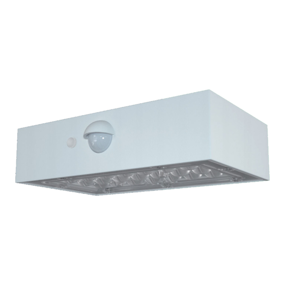
SOLAR LED WALL LIGHT
MULTI-LANGUAGE MANUAL QR CODE
Please scan the QR code to access the
manual in multiple languages.
Caution, risk of electric shock.
Advertisement
Table of Contents

Related Manuals for V-TAC VT-403


Summary of Contents for V-TAC VT-403
- Page 1 SOLAR LED WALL LIGHT INTRODUCTION Thank you for selecting and buying V-TAC product. V-TAC will serve you the best. Please read these instructions carefully before starting the installation and keep this manual handy for future refer- ence. If you have any another query, please contact our dealer or local vendor from whom you have purchased the product.
- Page 2 TECHNICAL DATA MODEL VT-403 10305, 10306 LUMENS 350 LM OUTPUT POWER EQUIVALENT WATT 30 W LEDs SMD 2835x21 pcs BATTARY 18650, 3.7V, 1200mAh, 4.44Wh MONO SOLAR PANEL DC 5.5V, 1.15W PIR SENSOR 120° x 6 Meters BEAM ANGLE 120° x 60°...
- Page 3 INSTALLATION Please use the measure card to mark holes position. 2. Drill 2 holes(6mm, depth 50mm) with a spacing of 80mm. 3. Fix the expansion plugs in the holes. 4. Fix the screws into the expansion plugs, allow the screws to protrude slightly around 3-5mm. 5.
Need help?
Do you have a question about the VT-403 and is the answer not in the manual?
Questions and answers