
Subscribe to Our Youtube Channel
Related Manuals for GUIL TORO D Series

Summary of Contents for GUIL TORO D Series
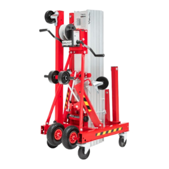
- Page 1 USER MANUAL TORO RANGE D MATERIAL LIFTERS TORO D-405/C TORO D-403/C TORO D-402/C ENGLISH GUIL - ENGINEERING FOR LIFTING LOADS...
-
Page 2: Table Of Contents
INTRODUCTION ® Thank you for having chosen a GUIL material lifter. Your TORO machine has been examined and checked before leaving our premises to ensure it is in absolutely perfect condition. To maintain this condition and to ensure a safe use, it is absolutely necessary for the user to read, understand and obey the safety and operating instructions in this manual as it contains information that will give you a thorough knowledge of the workings of your TORO lifter and guarantee maximum safety whilst operating it. -
Page 3: Owner And User's Obligations
® If either of the manuals are misplaced please contact your dealer or the manufacturer (GUIL SAFETY RECOMMENDATIONS Prior to set-up, be aware of and avoid the following hazardous situations: •... -
Page 4: Lifter Use Safety Instructions
If it were necessary to replace components, it is important that it is replaced with an original spare part. • Do not exceed the rated load capacity recommended by the manufacturer GUIL ® • Do not lift the load unless: the blocking hook is unhooked, all the stabiliser legs are correctly installed and the brakes on the wheels are activated. -
Page 5: Pre-Operation Inspection
The lifter can be used with the stabiliser legs installed in the front of the base (A) or in the back of the base (B). CAUTION! Check the work area for overhead obstructions or possible hazards before use (signs, cables, balconies, etc.). ALWAYS follow the set-up and working area and lifter use safety instructions in this manual. www.guil-lifters.com - GUIL -... -
Page 6: A.- Installation With Front Stabiliser Legs
4.2.- Unblock the levelling jack by loosening the M10 bolt found on the side of the leg. 4.3.- Adjust the levelling jacks until the legs are firm and free of wobbling, levelling the lifter from the front axis with the help of the spirit level. www.guil-lifters.com - GUIL -... - Page 7 ADJUSTING BOX BLOCKING LEVER 5.3 Adjust the levelling jacks until the legs are firm and free of wobbling, levelling the lifter from the sideways axis with the help of the spirit level. www.guil-lifters.com - GUIL -...
-
Page 8: B.- Installation With Back Stabiliser Legs
1.- Position the TORO lifter at the desired work site. 2.- Pull the stabiliser legs out of the base and insert them into the back sockets in the most extended position. The legs must always be set in the most extended position. www.guil-lifters.com - GUIL -... - Page 9 5.- Install the counterweight holder at the end of the back stabiliser legs and secure it using the magnetic locking bolts. MAGNETIC LOCKING BOLT 6.- Place 5 weights in the counterweight holder to a total of 100 kg. 5 weights of 20 kg www.guil-lifters.com - GUIL -...
-
Page 10: Reversing The Forks
2.- Raise and lower the lifter to check the following functions. 2.1.- Check that the winch is working correctly: 2.1.1.- It must operate smoothly and free of hesitation, binding or strange noises. 2.1.2.- All components must be present. 2.1.3.- And above all it, must brake perfectly. www.guil-lifters.com - GUIL -... -
Page 11: Moving The Lifter To The Work Area
IMPORTANT: Stop turning the winch handles when you notice that the movement becomes stiff. This indicates that the lifter has reached its maximum height. VERY DANGEROUS: Forcing the winch at this point could cause serious internal damage to the lifter. www.guil-lifters.com - GUIL -... -
Page 12: Lowering The Load
- Tilt the lifter slightly in the opposite direction to relieve the pressure of the blocking system. - Or slightly raise the lifter using the front stabiliser legs’ adjustable wheels, to release the pressure on the adjusting system. www.guil-lifters.com - GUIL -... -
Page 13: Transport
• Make sure wire sideways and the winch cable are free of dust and oxidation and grease them periodically, depending on the frequency the lifter is used. ® VERY IMPORTANT: Do not grease, lubricate or tamper with the winch. Consult with a GUIL technician. www.guil-lifters.com - GUIL -... -
Page 14: Risk Assesment
• Do not replace parts of the TORO lifter that are critical to stability or structure with items of different strength ® or specification. If it were necessary to replace parts, please contact your dealer or the manufacturer GUIL RISK ASSESMENT... - Page 15 CONDITIONS. 1.- DO NOT LIFT. THE STRAIGHT STABILISER LEGS DO NOT LOCK INTO THE HORIZONTAL POSITION. 2.- CONSULT A GUIL TECHNICIAN. 1.- DO NOT LIFT. THE STRAIGHT STABILISER LEGS 2.- LOOSEN THE LOCKING BOLT ON SCREW JACKS CANNOT BE THE SIDE, WITH THE ALLEN KEY.
- Page 16 HOOK. THE TELESCOPIC MASTS WON’T 2.- ENSURE THE CABLE IS SECURED TO RAISE. THE WINCH DRUM. 3.- CONSULT A GUIL TECHNICIAN. 1.- UNBLOCK THE BRAKES ON THE WHEELS. DIFFICULTIES IN MOVING THE 2.- CHECK THERE IS NOTHING LIFTER / NO LOAD.
- Page 17 POSITION THE TOWER TO WINCH HANDLE STICKS PREVENT DAMAGE TO THE OUT. HANDLE. LIFTER LOOSE IN THE SECURE THE LIFTER WITH TRANSPORT VEHICLE. SLINGS OR ROPES. THE LIFTER CANNOT BE USE SUITABLE LIFTING LOADED INTO THE VEHICLE. TECHNIQUES. www.guil-lifters.com - GUIL -...
-
Page 18: Guarantee
This warranty does not extend to any product which has been: - Subjected to misuse, neglect, accident or abuse. ® - Improperly repaired, altered or modified in any way without GUIL ’s specific permission. ® - Incorrectly operated; used in violation of instructions provided by GUIL ®... - Page 19 A1 ENGLISH page A3 INGENIERIA PARA LA ELEVACIÓN ENGINEERING FOR LIFTING LOADS P.I. La Creu C/ Ismael Tomás Alacreu 28 46250 L’Alcúdia SPAIN (VALENCIA) info@guil.es Tel: + 34. 96 299 65 00 Fax: + 34. 96 254 08 33 www.guil-lifters.com...
- Page 20 3.1.- Encajar los dos agujeros del soporte adaptador en los dos salientes que hay en la plancha de amarre del cabrestante. 3.2.- Fijar el soporte adaptador mediante los dos tornillos M10X20 que contiene el elevador TORO. www.guil-lifters.com - GUIL -...
- Page 21 IMPORTANTE: Para facilitar el encaje del taladro con el cuadradillo del prolongador, ayudarse girando la manivela del cabrestante. 6.- Bloquear el cabezal del taladro apretando la manivela lateral hasta que quede bien sujeto. 7.- Extraer la segunda manivela del cabrestante. 8.- Conectar el taladro y elevar. www.guil-lifters.com - GUIL -...
- Page 22 3.- Fit the drill support adaptor: 3.1.- Line up the two holes on the adaptor with the holes found on the winch support. 3.2.- Secure the support adaptor with the 2 M10X20 bolts supplied with the TORO lifter. www.guil-lifters.com - GUIL -...
- Page 23 6.- Lock the head of the drill using the red handle on the side until it is completely secured. 7.- Remove the second winch handle. 8.- Plug in the drill and lift the lifter. www.guil-lifters.com - GUIL -...
- Page 24 PIEZAS DE REPUESTO / REPLACEMENT PARTS LIST ® Para la obtención de piezas de repuesto, contacte con su distribuidor o con el fabricante (GUIL A continuación se muestran los planos de despiece para facilitar la tarea de la reposición de piezas.
- Page 27 TORO D-403/C TORO D-402/C INGENIERIA PARA LA ELEVACIÓN ENGINEERING FOR LIFTING LOADS P.I. La Creu C/ Ismael Tomás Alacreu 28 46250 L’Alcúdia SPAIN (VALENCIA) info@guil.es Tel: + 34. 96 299 65 00 Fax: + 34. 96 254 08 33 www.guil-lifters.com...
- Page 28 ® Ante cualquier duda o problema, no dude en ponerse en contacto con el fabricante GUIL This document is an annex to the User Manual and therefore the rules, warnings, suggestions etc. that are found in that document must also be applied to this document.
-
Page 29: Medidas / Measurements
(cm/in) 35.5 / 35.5 / 35.5 / Número de perfiles / Number of sections Carga máxima / Maximum load (Kg/lbs) 420 / 400 / 350 / Peso / Weight (Kg/lbs) 162 / 178 / 194 / www.guil-lifers.com - GUIL -... -
Page 30: Diagrama De Carga / Load Chart
60 / 310 / 70 / 280 / 70 / 340 / 80 / 320 / 80 / 260 / 90 / 300 / 90 / 230 / 100 / 280 / 100 / 200 / www.guil-lifters.com - GUIL -... - Page 31 0 to 24.8 in 37,5 cm ACT-05 BRAZO-GANCHO / LOAD HOOK 14.8 in ADAPTADOR PARA PERSIANAS Y de 0 a 60 cm PUERTAS ENROLLABLES / ACT-06 ADAPTOR TO INSTALL ROLLER DOOR from 0 to 23.6 in AND WINDOW SHUTTERS www.guil-lifers.com - GUIL -...
-
Page 32: Planos De Despiece / Exploded Drawings
– Ref. TORO D-405/C, TORO D-403/C, TORO D-402/C GUIL PLANOS DE DESPIECE / EXPLODED DRAWINGS El número de perfiles dependerá del modelo del elevador. The number of profiles will depend on the lifter’s model. www.guil-lifters.com - GUIL -... -
Page 33: Índice / Index
REF. 0003249 - BASE TORO C Y D / ................. B26 BASE TORO C AND D Nr. 14: REF. 0002303 - PATA DERECHA / ................. B27 RIGHT STABILISER LEG Nr. 15: REF. 0002304 - PATA IZQUIERDA / ................. B27 LEFT STABILISER LEG www.guil-lifers.com - GUIL -... -
Page 34: Planos / Drawings
TORO D-405/C COMPLETE TOWER REF. TORO D-403/C – TORO D-403/C TORRE COMPLETA / TORO D-403/C COMPLETE TOWER REF. TORO D-402/C – TORO D-402/C TORRE COMPLETA / TORO D-402/C COMPLETE TOWER 1A: TORO D-405/C 1B: TORO D-403/C 1C: TORO D-402/C www.guil-lifters.com - GUIL -... - Page 35 TENSOR DE 35 TORO C Y D 0002333 PASADOR IMANTADO CORTO 0000166 TORNILLO DIN912 M10X025 8.8 ZN 0000144 ARANDELA DIN125 M10 ZN 0000194 ARANDELA DIN9021 M10 ZN 0000195 TUERCA DIN985 M10 ZN 0000660 TORNILLO DIN912 M10X035 8.8 ZN www.guil-lifers.com - GUIL -...
- Page 36 REF. 0002467 - PERFILES ENSAMBLADOS TORO D-403/C / ASSEMBLED PROFILES TORO D-403/C REF. 0002469 - PERFILES ENSAMBLADOS TORO D-402/C / ASSEMBLED PROFILES TORO D-402/C Ref. 0002464 (TORO D−405/C) Ref. 0002467 (TORO D−403/C) Ref. 0002469 (TORO D−402/C) www.guil-lifters.com - GUIL -...
- Page 37 TUERCA DIN985 M12 ZN 0003249 BASE TORO C Y D 0000029 ARANDELA DIN9021 M12 ZN CBL-600 CABLE 07X19+0 DIAM. 6MM LONG.16 M CBL-TORO/ CABLE 07X19+0 DIAM. 6MM LONG.13 M D-403C CBL-TORO/ CABLE 07X19+0 DIAM. 6MM LONG.9,4 M C-301C www.guil-lifers.com - GUIL -...
- Page 38 – Ref. TORO D-405/C, TORO D-403/C, TORO D-402/C GUIL Nr. 3: REF. 0002311 - COMPONENTES CARRITO / FORK CARRIAGE COMPONENTS www.guil-lifters.com - GUIL -...
- Page 39 0001143 TORNILLO DIN7991 M04X16 10.9 ZN 0001142 TUERCA DIN985 M04 ZN 0000826 TUERCA DIN1587 M06 ZN 0001145 TORNILLO DIN912 M06X030 8.8 ZN 0000224 TORNILLO DIN912 M08X025 8.8 ZN 0002775 TUBO TERMORETRACTIL 9.5 MM ROJO 16 MM www.guil-lifers.com - GUIL -...
- Page 40 – Ref. TORO D-405/C, TORO D-403/C, TORO D-402/C GUIL Nr. 4: REF. 0002459 - COMPONENTES TRAMO I IZQUIERDA / 1st PROFILE COMPONENTS - LEFT www.guil-lifters.com - GUIL -...
- Page 41 0000617 POLEA DE COMPRA DE 60X10 0001407 PASADOR ELASTICO DIN1481 06X45 0000075 TORNILLO DIN7991 M08X020 10.9 ZN 0001362 ENGANCHE SUJETA CABLE ULK600XL 0001384 AMARRE CABLE ULK 600 XL 0002775 TUBO TERMORETRACTIL 9.5 MM ROJO 16 MM www.guil-lifers.com - GUIL -...
- Page 42 – Ref. TORO D-405/C, TORO D-403/C, TORO D-402/C GUIL Nr. 5: REF. 0002463 - COMPONENTES TRAMO I DERECHA / 1st PROFILE COMPONENTS - RIGHT www.guil-lifters.com - GUIL -...
- Page 43 0000617 POLEA DE COMPRA DE 60X10 0001407 PASADOR ELASTICO DIN1481 06X45 0000075 TORNILLO DIN7991 M08X020 10.9 ZN 0001362 ENGANCHE SUJETA CABLE ULK600XL 0001384 AMARRE CABLE ULK 600 XL 0002775 TUBO TERMORETRACTIL 9.5 MM ROJO 16 MM www.guil-lifers.com - GUIL -...
- Page 44 – Ref. TORO D-405/C, TORO D-403/C, TORO D-402/C GUIL Nr. 6: REF. 0002462 - COMPONENTES TRAMO II DERECHA / 2nd PROFILE COMPONENTS - RIGHT www.guil-lifters.com - GUIL -...
- Page 45 POLEA DE COMPRA DE 60X10 0001407 PASADOR ELASTICO DIN1481 06X45 0001687 REMACHE DIN7337 4,0X16 ALUMINIO 0002042 TORNILLO DIN7982 3.9X19 ZN 0001711 TAPITA ALUMINIO ULK 600 0001712 ENGANCHE TAPITA ALUMINIO 0002775 TUBO TERMORETRACTIL 9.5 MM ROJO 16 MM www.guil-lifers.com - GUIL -...
- Page 46 – Ref. TORO D-405/C, TORO D-403/C, TORO D-402/C GUIL Nr. 7: REF. 0002460 - COMPONENTES TRAMO II IZQUIERDA / 2nd PROFILE COMPONENTS - LEFT www.guil-lifters.com - GUIL -...
- Page 47 POLEA DE COMPRA DE 60X10 0001407 PASADOR ELASTICO DIN1481 06X45 0001687 REMACHE DIN7337 4,0X16 ALUMINIO 0002042 TORNILLO DIN7982 3.9X19 ZN 0001711 TAPITA ALUMINIO ULK 600 0001712 ENGANCHE TAPITA ALUMINIO 0002775 TUBO TERMORETRACTIL 9.5 MM ROJO 16 MM www.guil-lifers.com - GUIL -...
- Page 48 – Ref. TORO D-405/C, TORO D-403/C, TORO D-402/C GUIL Nr. 8: REF. 0002461 - COMPONENTES TRAMO III / 3rd PROFILE COMPONENTS www.guil-lifters.com - GUIL -...
- Page 49 TORNILLO DIN912 M10X120 8.8 ZN 0002423 PASADOR IMANTADO LARGO 0002319 RUEDAS MOVILES TORO C Y D BULL500/2 CABRESTANTE AUTOFRENABLE DOBLE PALANCA 0002413 NIVEL ACRILICO NT29 0001143 TORNILLO DIN7991 M04X016 10.9 ZN 0001142 TUERCA DIN985 M04 ZN www.guil-lifers.com - GUIL -...
- Page 50 TUERCA DIN985 M08 ZN 0000140 ARANDELA DIN9021 M08 ZN 0001857 EJE SEPARADOR – SISTEMA BLOQUEO 0001440 TORNILLO DIN912 M08X60 8.8 ZN 0000647 CARCASA SISTEMA BLOQUEO 0002859 MUELLE TRACCIÓN 13X8X25X1,2 0002332 GARRA DE SEGURIDAD IZQUIERDA 0002331 GARRA DE SEGURIDAD DERECHA www.guil-lifters.com - GUIL -...
- Page 51 ARANDELA DIN9021 M10 ZN 0000143 ARANDELA DIN127 M10 ZN 0000660 TORNILLO DIN912 M10X035 8.8 ZN 0001937 TORNILLO DIN912 M10X045 8.8 ZN 0000144 ARANDELA DIN125 M10 ZN 0000195 TUERCA DIN985 M10 ZN 0000668 BARRA ESTABILIZADORA ULK 800 XL www.guil-lifers.com - GUIL -...
- Page 52 0002339 TORNILLO DIN912 M10X080 8.8 ZN Nr. 12: REF. 0002319 - RUEDAS ABATIBLES / TRANSPORTATION WHEELS DENOMINACIÓN / DESCRIPTION CANT/QTY 0002326 SOLDADURA RUEDAS MOVILES 0003359 ARO 150 0000130 ARANDELA DIN125 M20 ZN 0002879 MANGO TRANSPORTE XL www.guil-lifters.com - GUIL -...
- Page 53 SEPARADOR RUEDA CORTO TORO C/D 0003250 ARO 260 IMPINCHABLE 0000130 ARANDELA DIN125 M20 ZN 0002310 TORNILLO DIN912 M08X10 8.8 ZN 0002129 TAPA GOMA INFORMACION 0001442 TORNILLO DIN912 M08X010 8.8 ZN 0000095 ARANDELA DIN125 M08 ZN 0003357 RUEDA 150 PLETINA FRENO www.guil-lifers.com - GUIL -...
- Page 54 HUSILLO PATA TORO 0001925 ARANDELA HUSILLO PATA TORO 0003358 RUEDA 150 AGUJERO PASANTE FRENO 0000194 ARANDELA DIN9021 M10 ZN 0000143 ARANDELA DIN127 M10 ZN 0000660 TORNILLO DIN912 M10X035 8.8 ZN 0001674 TORNILLO DIN912 M10X016 8.8 ZN www.guil-lifters.com - GUIL -...
-
Page 55: Declaración De Conformidad Ce / Ec-Certificate Of Conformity
– Ref. TORO D-405/C, TORO D-403/C, TORO D-402/C GUIL DECLARACIÓN DE CONFORMIDAD CE / EC-CERTIFICATE OF CONFORMITY www.guil-lifers.com - GUIL -... -
Page 56: Libro De Mantenimiento / Maintenance Record
Servicio realizado por / Checked by: Fecha / Date: Operación / Tested elements: Servicio realizado por / Checked by: Fecha / Date: Operación / Tested elements: Servicio realizado por / Checked by: Fecha / Date: Operación / Tested elements: www.guil-lifters.com - GUIL -... - Page 57 Servicio realizado por / Checked by: Fecha / Date: Operación / Tested elements: Servicio realizado por / Checked by: Fecha / Date: Operación / Tested elements: Servicio realizado por / Checked by: Fecha / Date: Operación / Tested elements: www.guil-lifers.com - GUIL -...
- Page 58 VAT No ES- B96498829 P.I. La Creu C/ Ismael Tomás Alacreu, 28 46250 L’Alcúdia (VALENCIA) SPAIN Tel: + 34. 96 299 65 00 Fax: + 34. 96 254 08 33 www.guil-lifters.com info@guil.es Fecha de edición de este manual / Manual edition date: 11/2020...
Need help?
Do you have a question about the TORO D Series and is the answer not in the manual?
Questions and answers