
Subscribe to Our Youtube Channel
Related Manuals for ECOWITT WN67


Summary of Contents for ECOWITT WN67
- Page 1 5 IN 1 PROFESSIONAL WEATHER STATION (NO SOLAR POWERED AND NO UV SENSOR) Model: WN67...
- Page 2 QR perleggi il manuale italiano e conservalo perReferenza futura Instruction manuals https://s.ecowitt.com/46Y36A Help Our product is continuously changing and improving, particularly online services and associated applications. To download the latest manual and additional help, please contact our technical support team: support@ecowitt.com support.eu@ecowitt.net (EU/UK)
-
Page 3: Table Of Contents
Table of Contents 1 Introduction ....................3 2 Warnings and Cautions ................3 3 Pre-Installation Checkout and Site Survey ..........3 3.1 Pre-Installation Checkout ..............3 3.2 Site Survey ....................3 4 Getting Started ..................... 4 4.1 Contents ....................4 4.2 Sensor Array Set Up ................5 4.2.1 Install U-bolts and mounting pole............5 4.2.2 Install wind vane................ -
Page 4: Introduction
1 Introduction Thank you for your purchase of this Weather Station. The following user guide provides step-by-step instructions for installation, operation, and troubleshooting. 2 Warnings and Cautions Warning: Any metal object may attract a lightning strike, including your weather station mounting pole. Never install the weather station in a storm. Warning: Installing your weather station in a high location may result in injury or death. -
Page 5: Getting Started
or rooftop. 3. Avoid wind and rain obstructions. The rule of thumb is to install the sensor array at least four times the distance of the height of the tallest obstruction. For example, if the building is 20’ tall, and the mounting pole is 6’... -
Page 6: Sensor Array Set Up
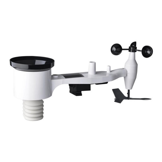
Table 1: Package content 4.2 Sensor Array Set Up Figure 1: Sensor assembly components Wind speed cups Antenna Wind vane U-Bolts Thermo- and hygro-meter Battery compartment door sensors Rain collector Reset button Bubble level 10 LED (red) to indicate data transmission Table 2: Sensor assembly detailed items 4.2.1 Install U-bolts and mounting pole... - Page 7 the U-bolt ends. The metal plate, visible in Figure 2, has four holes through which the ends of the two U-Bolts will fit. The plate itself is inserted in a groove on the bottom of the unit. Note that one side of the plate has a straight edge (which goes into the groove), the other side is bent at a 90-degree angle and has a curved profile (which will end up “hugging”...
-
Page 8: Install Wind Vane
4.2.2 Install wind vane Push the wind vane onto the shaft on the bottom of the sensor, until it stops moving further, as shown in figure 4. Tighten the set screw, with a Philips screwdriver (size PH0), until the wind van cannot be removed from the axle, as shown in figure 4. -
Page 9: Install Rain Gauge
4.2.4 Install Rain Gauge Install the rain gauge funnel. Rotate clockwise to attach the funnel to the outdoor sensor. Figure 6: Rain gauge installation and maintenance 4.2.5 Install Batteries Insert 2 AA batteries in the battery compartment. The LED indicator on the back of the transmitter will turn on for four seconds and normally flash once every 16 seconds (the sensor transmission update period). -
Page 10: Mount Assembled Outdoor Sensor Package
Figure 7: Battery installation diagram Note: If no LED light up or is permanently on, make sure the batteries are inserted the correct way or a proper reset has happened. Do not install the batteries backward. You can permanently damage the outdoor sensor Note: We recommend 1.5V lithium batteries for cold weather climates, but alkaline batteries are enough for most climates. - Page 11 4.2.6.2 Mounting You can attach a pipe to a permanent structure and then attach the sensor package to it (see Figure 8). The U-Bolts will accommodate a pipe diameter of 1-2 inches (pipe not included). Figure 8: Sensor package mounting diagram Finally, place the sensor package on top of the prepared mounting pipe.
-
Page 12: Reset Button And Transmitter Led
4.2.7 Reset Button and Transmitter LED In the event that the sensor array is not transmitting, reset the sensor array. With an open-ended paperclip, press and hold the RESET BUTTON for three seconds and resynchronize with the console by powering down and up the console. -
Page 13: Troubleshooting Guide
1. Clean the rain gauge once every 3 months. Rotate the funnel counter-clockwise and lift to expose the rain gauge mechanism, and clean with a damp cloth. Remove any dirt, debris and insects. If bug infestation is an issue, spray the array lightly with insecticide. Figure 10: Rain gauge installation and maintenance 2. - Page 14 Problem Solution The outdoor sensor The sensor array may have initiated properly and array does not the data is registered by the console as invalid, communicate with the and the console must be reset. Press the reset display console.. button as described in Section 5.2. With an open-ended paperclip, press the reset button for 3 seconds to resync the console with the sensor array about 10 feet away.
-
Page 15: Warranty Information
rain when it is not mounting pole) may result in the tipping bucket raining incorrectly incrementing rainfall. Make sure you have a stable, level mounting solution. 8 Warranty Information We disclaim any responsibility for any technical error or printing error, or their consequences.
Need help?
Do you have a question about the WN67 and is the answer not in the manual?
Questions and answers