Table of Contents
Advertisement
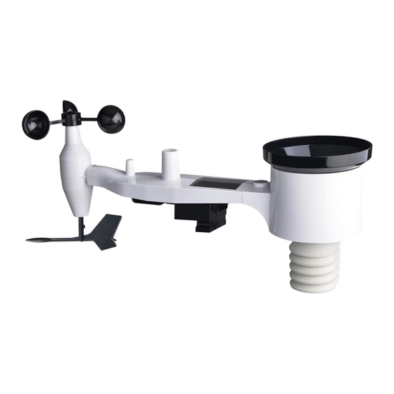
7-IN-1 WIRELESS SOLAR POWERED
WEATHER SENSOR
Operation Manual
Model: WS69
Thank you for purchasing this 7-in-1 Wireless Solar Powered Weather
Sensor ( built-in: Thermo-hygrometer / Rain Gauge / Wind Speed Sensor/
Wind Direction Sensor, Light and UV sensor, Solar panel Sensor )! This
unit measures outdoor temperature and humidity, wind direction, rainfall,
wind speed, wind gust, UV & light, Solar light intensity and UV index
data. The data can be received by the Wi-Fi gateway(sold separately) and
can be viewed using the WS View Plus/ Ecowitt App mobile application
(after Wi-Fi configuration on the gateway has been completed).
To ensure the best product performance, please read this manual and
retain it for future reference.
Advertisement
Table of Contents

Related Manuals for ECOWITT WS69


Summary of Contents for ECOWITT WS69
- Page 1 UV & light, Solar light intensity and UV index data. The data can be received by the Wi-Fi gateway(sold separately) and can be viewed using the WS View Plus/ Ecowitt App mobile application (after Wi-Fi configuration on the gateway has been completed).
- Page 2 QR perleggi il manuale italianoe conservalo perReferenza futura Instruction manuals https://www.ecowitt.com/support/download/180 Help Our product is continuously changing and improving, particularly online services and associated applications. To download the latest manual and additional help, please contact our technical support team: support@ecowitt.com support.eu@ecowitt.net (EU/UK)
-
Page 3: Table Of Contents
1 Table of Contents 1 TABLE OF CONTENTS ................1 2 WARNINGS AND CAUTIONS ............2 3 UNPACKING ..................3 4 FEATURES .................... 4 5 SET UP GUIDE ..................5 5.1 P ............5 NSTALLATION HECKOUT 5.2 S ..................5 URVEY 5.3 S ............6 ENSOR ACKAGE... -
Page 4: Warnings And Cautions
2 Warnings and Cautions Warning: Any metal object may attract a lightning strike, including your weather station mounting pole. Never install the weather station in a storm. If you are mounting the weather station to a house or structure, ... -
Page 5: Unpacking
3 Unpacking Open your weather station box and inspect that the contents are intact (nothing broken) and complete (nothing missing). Inside you should find the following: Item Description Outdoor Sensor Body with built-in: Thermo-hygrometer / Rain Gauge / Wind Speed Sensor/ Wind Direction Sensor, Light and UV sensor, Solar panel Wind speed cups (to be attached to outdoor sensor body) Wind vane (to be attached to outdoor sensor body) -
Page 6: Features
No display, need to work with the WIFI gateway to complete the WIFI configuration on our WS View Plus/ Ecowitt App. After the WIFI configuration, the live weather data can be viewed directly on the WS View Plus/ Ecowitt App. -
Page 7: Set Up Guide
5 Set up Guide 5.1 Pre Installation Checkout To complete assembly you will need a Philips screwdriver (size PH0) and a wrench (size M6; included in package). Note: We suggest you assemble all components of the weather station, including console in one location so you can easily test functionality. -
Page 8: Sensor Package Assembly
batteries every 2-3 years. Provide easy access to the weather station. 2. Avoid radiant heat transfer from buildings and structures. In general, install the sensor array at least 5’ or 1.52m from any building, structure, ground, or roof top. 3. Avoid wind and rain obstructions. The rule of thumb is to install the sensor array at least four times the distance of the height of the tallest obstruction. -
Page 9: Install U-Bolts And Metal Plate
Figure 1: Sensor assembly components 1 Wind speed cups 7 Light sensor and UV sensor 2 Wind vane 8 U-Bolts 3 Thermo- and hygro-meter sensors 9 Battery compartment door 4 Rain collector 10 Reset button 5 Bubble level 11 LED (red) to indicate data transmission 6 Solar panel Table 2: Sensor assembly detailed items... - Page 10 and has a curved profile (which will end up “hugging” the mounting pole). Once the metal plate is inserted, remove nuts from the U-Bolts and insert both U-bolts through the respective holes of the metal plate as shown in Figure 2. Figure 2: U-Bolt installation Loosely screw on the nuts on the ends of the U-bolts.
-
Page 11: Install Wind Vane
5.3.2 Install wind vane Push the wind vane onto the shaft on the bottom side of the sensor package, until it goes no further, as shown on the left side in Figure 4. Next, tighten the set screw, with a Philips screwdriver (size PH0), as shown on the right side, until the wind vane cannot be removed from the axle. -
Page 12: Install Batteries In Sensor Package
Figure 5: Wind speed cup installation diagram 5.3.4 Install Batteries in sensor package Open the battery compartment with a screwdriver and insert 2 AA batteries in the battery compartment. The LED indicator on the back of the sensor package (item 9) will turn on for four seconds and then flash once every 16 seconds indicating sensor data transmission. -
Page 13: Mount Assembled Outdoor Sensor Package
Note: We recommend Lithium batteries for cold weather climates, but alkaline batteries are sufficient for most climates. Rechargeable batteries have lower voltages and should never be used. 5.3.5 Mount assembled outdoor sensor package 5.3.5.1 Before you mount Before proceeding with the outdoor mounting detailed in this section, you may want to skip to setup instructions in section 5.5 and onwards first, while you keep the assembled outdoor sensor package nearby (although preferably not closer than 5 ft. - Page 14 5.3.5.2 Mounting You can attach a pipe to a permanent structure and then attach the sensor package to it (see Figure 7). The U-Bolts will accommodate a pipe diameter of 1-2 inches (pipe not included). Figure 7: Sensor package mounting diagram Make sure the mounting pipe is vertical, or very close to it.
- Page 15 orientation, lightly tighten the bolts a little more (use a wrench) to prevent further rotation. Note: The orientation to WEST is necessary for two reasons. The most important one is to position the solar panel and light sensor in the most advantageous position for recording solar radiation and charging internal capacitors.
-
Page 16: Reset Button And Transmitter Led
times and consequently the console may have registered rainfall that did not really exist. You can use console functions to clear this from history. Doing so is also important to avoid false registration of these readings with weather services. 5.3.6 Reset Button and Transmitter LED In the event the sensor array is not transmitting, reset the sensor array. - Page 17 sensors and experience intermittent communication between sensor package and console, try turning off these other devices for troubleshooting purposes. You may need to relocate the transmitters or receivers to avoid the interference and establish reliable communication. The frequencies used by the sensors are one of (depending on your location): 433, 868, or 915 MHz (915 MHz for United States).
-
Page 18: Setup Guide Using Wi-Fi Gateway
6 Setup Guide using Wi-Fi Gateway If you wish to view the sensor data on your mobile device, you need to pair this sensor device with the Wi-Fi gateway (sold separately), or another compatible display console device(sold separately). Before you can use the mobile application to connect to the Wi-Fi gateway, it must be configured on your Wi-Fi network. -
Page 19: Maintenance
7 Maintenance The following steps should be taken for proper maintenance of your station 1. Clean the rain gauge once every 3 months. Rotate the funnel counter-clockwise and lift to expose the rain gauge mechanism, and clean with a damp cloth. Remove any dirt, debris and insects. If bug infestation is an issue, spray the array lightly with insecticide. - Page 20 3. When replacing the batteries, apply a corrosion preventing compound on the battery terminals, available at Amazon and most hardware stores. 4. In snowy environments, spray the top of the weather station with anti-icing silicon spray to prevent snow build up.
-
Page 21: Specifications
8 Specifications Note: Out of range values will be displayed using “---”: Outdoor 7-in-1 sensor Specification Transmission distance 100 m (330 ft.) open field RF Frequency 433/868/915 depending location Temperature range -40°C – 60°C (-40°F - 140°F) Temperature accuracy ± 1°C, or ± 2°F Temperature resolution 0.1°C, or 0.1°F Humidity range... - Page 22 Power Specification 7-in-1 weather sensor Solar panel (built-in) 7-in-1 weather sensor 2 x AA 1.5V LR6 Alkaline (not included), or (backup) 2 x AA 1.5V Lithium battery (not included) Table 5: Power specification The primary power source for the outdoor sensor is the solar panel. When available solar power (light over recent period) is insufficient, the batteries will be used.
-
Page 23: Warranty Information
9 Warranty Information We disclaim any responsibility for any technical error or printing error, or the consequences thereof. All trademarks and patents are recognized. We provide a 1-year limited warranty on this product against manufacturing defects, or defects in materials and workmanship. This limited warranty begins on the original date of purchase, is valid only on products purchased, and only to the original purchaser of this product.
Need help?
Do you have a question about the WS69 and is the answer not in the manual?
Questions and answers