
Related Manuals for NEC LED-FE012i3


Summary of Contents for NEC LED-FE012i3
- Page 1 User’s Manual LED Module [Models for indoor use] LED-FE012i3 LED-FE015i3 LED-FE019i3 MODELS: LED-FE012i3, LED-FE015i3, LED-FE019i3...
-
Page 2: Table Of Contents
Table of Contents Important Information ..............English-1 Contents ..................English-5 Related Items for Installation ............English-6 Parts Name and Functions ..............English-7 Specifications .................English-9 Diagram ..................English-10 NOTE: (1) The contents of this manual may not be reprinted in part or whole without permission. (2) The contents of this manual are subject to change without notice. (3) Great care has been taken in the preparation of this manual;... -
Page 3: Important Information
Important Information Safety Precautions and Maintenance FOR OPTIMUM PERFORMANCE, PLEASE NOTE THE FOLLOWING WHEN SETTING UP AND USING THE LED DISPLAY SYSTEM: About the Symbols To ensure safe and proper use of the product, this manual uses a number of symbols to prevent injury to you and others as well as damage to property. - Page 4 ● Be sure to read the following before using the product to use it correctly and safely. WARNING Make sure there are enough people available Do not apply vibrations or shocks to the to ensure safety (at least two people) when product.
- Page 5 CAUTION Do not use or store the product in the When connecting the power cord to the following places. product’s AC IN terminal, make sure the • Near heaters connector is fully and firmly inserted. • Places with lots of humidity or dust, or Do not damage the power cord.
- Page 6 Recommended Use & Maintenance About the LED lamps The surface of the pixel card is vulnerable to shocks, so do not press or hit the surface. LED lamps are sensitive to static electricity and surge voltage, which may damage their components and decrease their reliability.
-
Page 7: Contents
Contents The supplied parts are as follows. In case one of these parts is missing or damaged, contact the retailer. CAUTION Depending on the system you ordered, there is a cabinet without the upper connector. [Cabinet] [Pixel card] 8 cards per cabinet English - 5... -
Page 8: Related Items For Installation
Related Items for Installation The items required when installing the system are shown below. Contact your retailer for more details. [Power cord] To connect the LED module to the power distributor [LAN cable] To connect two LED modules together (750 mm for vertical connection, 1000 mm for horizontal connection) [Cabinet alignment bracket] [Screw for Adjustment plates] [Connection screw for LED modules]... -
Page 9: Parts Name And Functions
Parts Name and Functions ④ ① ② ⑩ Front Rear ⑨ ⑤ ⑧ ⑥ ③ ⑦ Name Description Interface connectors Input and output connectors for the signal and AC power. To input the signal from the LED controller or the previous LED module. 12 Signal input/output When a signal is input into 1, the signal is output from 2. - Page 10 There are three types of cabinets. (1) When using other than the top (Type A) The connectors are equipped on the top and bottom sides. There are guide pins on the top. Receiving Power unit card (2) When used at the top (Type B) There are no connectors on the top side.
-
Page 11: Specifications
Specifications LED-FE012i3 LED-FE015i3 LED-FE019i3 LED configuration 3-in-1 Flip chip SMD Pixel pitch 1.27 mm 1.58 mm 1.90 mm Number of displayed pixels (resolution/module) 480×270 384×216 320×180 Brightness 700 cd/m Contrast ratio 8000:1 Brightness adjustment range 0 to 100% (256 increments) Gamma correction 1.0 to 4.0 (default setting: 2.8) -
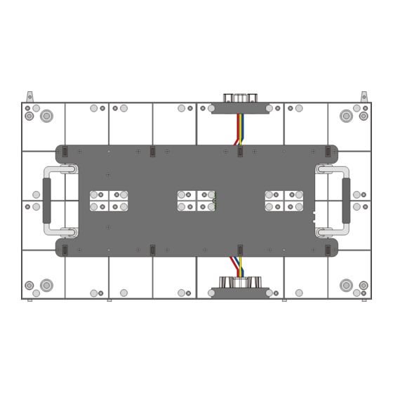
Page 12: Diagram
Diagram LED-FE012i3, LED-FE015i3, LED-FE019i3 Rear 4 x M8 18.5 (Unit: mm) English - 10... - Page 13 Adjustment plate 4-Φ8.5 (Unit: mm) English - 11...
- Page 14 According to EU directive 2006/66/EC and amendments, the battery can’t be disposed improperly. The battery shall be separated to collect by local service. Service & Support in Europe Please contact: Sharp NEC Display Solutions Europe GmbH. Landshuter Allee 12-14, D-80637 München Phone: + 49 (0) 89/99699-0...
Need help?
Do you have a question about the LED-FE012i3 and is the answer not in the manual?
Questions and answers