Table of Contents
Advertisement
ALIMENTATION 240 VAC POWER SUPPLY
MULTI POSITION
INSTALLER / SERVICE TECHNICIAN:
USE THE INFORMATION IN THIS MANUAL FOR THE INSTALLATION AND
SERVICING OF THE FURNACE AND KEEP THE DOCUMENT NEAR THE
UNIT FOR FUTURE REFERENCE.
HOMEOWNER:
PLEASE KEEP THIS MANUAL NEAR THE FURNACE FOR FUTURE
REFERENCE.
Printed in Canada
Printed on 100% recycled paper
2012-07-03
Models:
FEM10-M2301CM-B
FEM15-M2301CM-B
FEM18-M2301CM-B
FEM20-M2301CM-B
FEM23-M2301CM-B
FEM20-M2301DM-B
FEM23-M2301DM-B
FEM27-M2301DM-B
Caution: Do not tamper with
the unit or its controls. Call a
qualified service technician.
Manufactured by:
Industries Dettson inc.
3400 Industrial Boulevard
Sherbrooke, Quebec - Canada
J1L 1V8
X40163 Rev. G
Advertisement
Table of Contents

Summary of Contents for SUPREME FEM10-M2301CM-B
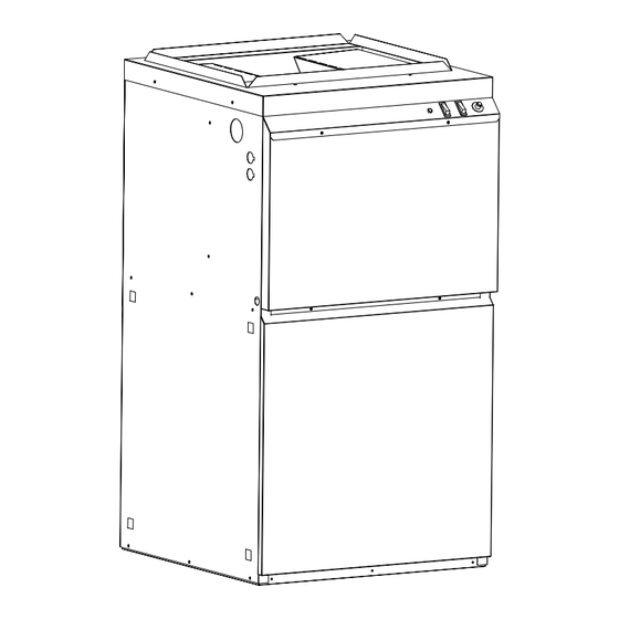
- Page 1 ALIMENTATION 240 VAC POWER SUPPLY Models: MULTI POSITION FEM10-M2301CM-B FEM15-M2301CM-B FEM18-M2301CM-B FEM20-M2301CM-B FEM23-M2301CM-B FEM20-M2301DM-B FEM23-M2301DM-B FEM27-M2301DM-B Caution: Do not tamper with INSTALLER / SERVICE TECHNICIAN: the unit or its controls. Call a qualified service technician. USE THE INFORMATION IN THIS MANUAL FOR THE INSTALLATION AND...
-
Page 2: Table Of Contents
Table 4 : Airflow (CFM) - SUPREME with 1/3HP motor..10 DANGER OF FREEZING ........3 Table 5 : Airlfow (CFM) - SUPREME with 1HP motor..10 INSTALLATION............. 3 Table 6 : PARTS LIST, Supreme with 1/3 HP and 1 HP motor: FEMxx-M2401AM-B or POSITIONING THE FURNACE......4 FEMxx-M2401BM-B ...........14 CLEARANCES TO COMBUSTIBLE MATERIAL .. -
Page 3: Safety
Ask the technician installing your furnace to show SAFETY and explain to you the following items: The main disconnect switch or circuit breaker; DANGER, WARNING AND CAUTION The air filter and how to change it (check The words DANGER, WARNING and CAUTION are used to monthly and clean or replace if necessary);... -
Page 4: Positioning The Furnace
POSITIONING THE FURNACE Figure 1: Upflow installation WARNING Fire and explosion hazard. The furnace must be installed in a level position, never where it will slope toward the front. Do not store or use gasoline or any other flammable substances near the furnace. Non-observance of these instructions will potentially result in death, bodily injury and/or property damage. -
Page 5: Electrical System
Once the current has stabilized, a reading should be taken and the anticipator adjusted to that value. The SUPREME furnace is completely pre-wired and all field longer heating cycles are desired, the anticipator can be wiring must be connected to the terminal blocks on the unit. -
Page 6: Ducts And Filters
HIGH If the heating and air-cooling speed are the same, the red The SUPREME furnace is equipped with a filter frame for the wire and the blue wire can be connected on the same blower compartment. It must be installed on the outside of terminal on the motor. -
Page 7: Use Of A Heat Pump
Figure 8 : Manual Furnace Controls during a call for heat. Refer to the wiring diagrams for the location of the relay (RAcc) on the control panel. 2.7.2. Use of a heat pump When using a heat pump, a thermostat with dial fuel option or a fossil fuel kit is required that prevents the operation of the electric elements and the heat pump at the same time. -
Page 8: Supply Air Temperature Rise Test
0.82 x amps. x volts Remove the obstruction and the elements should restart Liter/s= ------------------------- after a few minutes. Diff. temperature ˚C 3.1 x amps. x volts CFM = ------------------------ MAINTENANCE Diff. temperature ˚F 3.4.1. Supply Air Temperature Rise Test WARNING Operate the unit at maximum power for at least 10 Electrical shock hazard. -
Page 9: Furnace Information
FURNACE INFORMATION Model: Serial number: Furnace installation date: Service telephone # - Day: Night: Dealer name and address: START-UP RESULTS Voltage: Total current consumed by the elements: Supply air temperature: Return air temperature: Supply air duct static pressure: Return air duct static pressure: Total pressure: Calculated air flow: Current consumed by the blower motor:... -
Page 10: Table 3 : Technical Specifications
3 tons 5 tons 1) Select a blower speed that will generate the specified temperature rise 2) Calculated on the basis of Norm C22.2 Nr. 236 Table 4 : Airflow (CFM) - SUPREME with 1/3HP motor Static Pressure Blower Speed MED-LOW... -
Page 11: Figure 9 : Furnace Dimensions
Figure 9 : Furnace dimensions DNS-0982 Rev C Figure 10 : Wiring diagram, 3 wires DNS-1206 Rev.A... -
Page 12: Figure 11 : Wiring Diagram, Continuation
Figure 11 : Wiring diagram, continuation DNS-1206 Rev.A... -
Page 13: Figure 12 : Parts List, Supreme With 1/3 Hp And 1 Hp
Figure 12 : PARTS LIST, Supreme with 1/3 HP and 1 HP motor: FEMxx-M2401AM-B or FEMxx-M2401BM-B B50090C.dwg... -
Page 14: Table 6 : Parts List, Supreme With 1/3 Hp And 1 Hp
Table 6: PARTS LIST, Supreme with 1/3 HP and 1 HP motor: FEMxx-M2401AM-B or FEMxx-M2401BM-B ITEM PART # DESCRIPTION COMMENTS B03274-01 HEATING ELEMENT PLATE ASSEMBLY FEM-10kW (1/3 HP) Item 11 included B03275-01 HEATING ELEMENT PLATE ASSEMBLY FEM-15kW (1/3 HP) Item 11 included...


Need help?
Do you have a question about the FEM10-M2301CM-B and is the answer not in the manual?
Questions and answers