
Related Manuals for SteelMax BM-18


Summary of Contents for SteelMax BM-18
- Page 1 The tools of innovation. OPERATOR’S MANUAL BM-18 BEVELING MACHINE 801 W. Mineral Ave. Suite 103 Littleton, CO 80120 1– 303 – 690 - 9146, FAX 303 – 690 – 9172 www.steelmax.com sales@steelmax.com...
-
Page 2: Table Of Contents
Contents 1. GENERAL INFORMATION ....................3 1.1. Application ........................3 1.2. Technical data ......................3 1.3. Equipment included ...................... 4 1.4. Dimensions ........................4 1.5. Design ........................... 5 2. SAFETY PRECAUTIONS ....................6 3. SYMBOLS ..........................8 4. STARTUP AND OPERATION ....................9 4.1. -
Page 3: General Information
1. GENERAL INFORMATION 1.1. Application The BM-18 is a beveling machine designed to bevel plates and pipes made of steel, aluminum alloys, brass, or plastics. Depending on the milling head, the machine allows you to bevel at the angle of 22.5°, 30°, 37.5°, 45°, 50°, 55°, or 60°. -
Page 4: Equipment Included
1 unit 6 mm hex wrench 1 unit 32 mm flat wrench 1 unit Grease for screws (5 g, 0.17 oz) 1 unit – Operator’s Manual 1 unit 1.4. Dimensions 23″ (585 mm) 6 9/64″ (156 mm) BM-18 Operator’s Manual... -
Page 5: Design
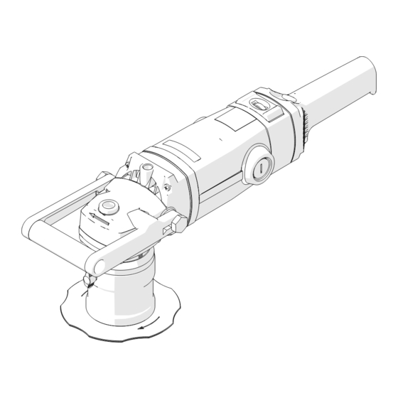
BM-18 1.5. Design Handle Switch lock Speed dial Air vents Handle Sleeve ON/OFF switch Clamping screw Guide Roller Milling head BM-18 Operator’s Manual... -
Page 6: Safety Precautions
Do not remove chips with bare hands. 20. Maintain the machine and install/remove parts and tools only after you unplug the machine from the power source. 21. Repair only in a service center appointed by the seller. BM-18 Operator’s Manual... - Page 7 23. If you are not going to use the machine, remove it from the work area and keep it in a safe and dry place. 24. If you are not going to use the machine for an extended period, put anti-corrosion material on the steel parts. BM-18 Operator’s Manual...
-
Page 8: Symbols
BM-18 3. SYMBOLS Before using the machine, familiarize yourself with the following symbols (tab. 1). Use eyes protection Use hearing protection Read the Operator’s Manual Warning against electric voltage Tab. 1. Explanation of symbols BM-18 Operator’s Manual... -
Page 9: Startup And Operation
BM-18 4. STARTUP AND OPERATION 4.1. Removing and installing the milling head Unplug the power cord. To remove the milling head, continue in the following se- quence. 6 mm 32 mm BM-18 Operator’s Manual... - Page 10 BM-18 To install the milling head, remove the sleeve as shown before. Then, continue in the sequence that follows. Make sure that the milling head aligns with the spindle (3). 6 mm 32 mm BM-18 Operator’s Manual...
-
Page 11: Adjusting The Bevel Width
12.6 14.1 15.6 17.4 11.9 12.7 13.9 15.6 17.1 18.0 13.0 13.9 15.1 17.0 18.0 14.1 15.0 16.4 18.0 15.2 16.2 17.6 Tab. 1. Relation between the bevel width and bevel height for the available milling heads BM-18 Operator’s Manual... -
Page 12: Adjusting The Guide For Beveling With Radius
Setting Speed 1800 rpm 2400 rpm 3100 rpm 3800 rpm 4500 rpm 5850 rpm To machine structural steel of standard quality or quality steel, set the speed to 4 and decrease the speed if much sparking occurs. BM-18 Operator’s Manual... -
Page 13: Operating
After the work is finished, release the ON/OFF switch to turn off the motor. Then, wait until the rotation stops and unplug the power cord. Clean the machine with a dry cotton cloth and no chemical agents. BM-18 Operator’s Manual... -
Page 14: Replacing The Cutting Inserts
Make sure that the bottom of each insert is in full contact with the socket (5). ✓ CORRECT × INCORRECT Every week clean the threads of the mounting screws for inserts and put the sup- plied grease on the threads. BM-18 Operator’s Manual... -
Page 15: Replacing The Roller
0.2–0.6 mm between the roller and the cutting inserts. The number of washers needed depends on the milling head. Put all unused washers between the circlip and the roller. ✓ CORRECT Unused wash- 0.2–0.6 mm Distance wash- × INCORRECT (collision between roller and cutting in- sert) BM-18 Operator’s Manual... -
Page 16: Replacing The Radius Roller
Make sure that the roller turns freely. × × ✓ CORRECT INCORRECT INCORRECT (collision be- (too large gap tween roller between roller and cutting in- and cutting in- sert) sert) BM-18 Operator’s Manual... -
Page 17: Replacing The Brushes
If the brush is shorter than 10 mm (0.4″), replace the two brushes with new ones. Install in reverse sequence. Then, let the motor operate with no load for 20 minutes. BM-18 Operator’s Manual... -
Page 18: Accessories
Allows for external beveling of pipes with diameters of at least 150 mm (5 29/32″) and internal beveling of pipes with diameters of at least 110 mm (4 21/64″). Part number: PRW-0670-05-00-00-0 Pipe attachment 1 unit M5x12 screw 3 units 6 mm hex wrench 1 unit T25 torx wrench 1 unit BM-18 Operator’s Manual... - Page 19 BM-18 To install, unplug the power cord. Use heat to increase the temperature of the screws. Use the T25 torx wrench to remove the standard guide, and then install the pipe at- tachment. BM-18 Operator’s Manual...
- Page 20 (4) equally to the pipe. Tighten the rollers in this position. Next, move the ma- chine from the pipe and set the required parameters (5). Then, start the machine, slowly move it to the pipe, and bevel in the direction (6). BM-18 Operator’s Manual...
-
Page 21: Sticker Against Scratches
(2). Unplug the power cord and turn the sleeve to set ‘0’ on the scale. Next, put the machine with a beveling milling head into the fixture (3) so that the motor is on the support (4). BM-18 Operator’s Manual... - Page 22 BM-18 BM-18 Operator’s Manual...
- Page 23 Use the 5 mm hex wrench to loosen the horizontal clamp (1), and then put the workpiece (2) so that it makes contact with the guide (3). Move the horizontal clamp to the workpiece (4) and tighten the screws in this position (5). BM-18 Operator’s Manual...
- Page 24 Then, use the 5 mm hex wrench to tighten the screws (5) to attach the machine. Start the machine and set the required rotational speed. Then, put the workpiece on the left and bevel in the direction (6). BM-18 Operator’s Manual...
-
Page 25: Radius Insert Positioner
Put the positioner from the top (1) so that the edge marked with a given radius aligns with the edges of three cutting inserts with the same radius (2). Turn the sleeve (3) until the guide is in contact with the positioner (4). BM-18 Operator’s Manual... -
Page 26: Milling Tools
Radius insert R3 (4 required, sold per 10 in a set) PLY-000160 Radius insert R4 (4 required, sold per 10 in a set) PLY-000161 Radius insert R5 (4 required, sold per 10 in a set) SRB-000289 Mounting screw for radius insert BM-18 Operator’s Manual... -
Page 27: Spare And Wearing Parts
Carbon brush for 110 V SCZ-000030 Carbon brush for 230 V KLC-0509-13-00-00-0 32 mm flat wrench KLC-000009 6 mm hex wrench KLC-000028 T15 torx screwdriver SMR-000005 Grease for mounting screws (5 g, 0.17 oz) RLK-0640-99-02-00-0 Beveling roller RLK-0640-99-03-00-0 Radius roller BM-18 Operator’s Manual... -
Page 28: Exploded Views And Parts List
BEVELING INSERT FOR ALUMINIUM – SRB-000290 MOUNTING SCREW FOR BEVELING INSERT – PLY-000737 RADIUS INSERT R2 – PLY-000738 RADIUS INSERT R3 – PLY-000739 RADIUS INSERT R4 – PLY-000740 RADIUS INSERT R5 – SRB-000289 MOUNTING SCREW FOR RADIUS INSERT – optional BM-18 Operator’s Manual... - Page 29 BM-18 ITEM PART NUMBER DESCRIPTION Q-TY TLJ-0670-04-00-00-0 SLIDING SLEEVE PRW-0670-03-00-00-0 GUIDE TLJ-0509-01-01-00-1 SPINDLE SLEEVE RLK-0640-99-02-00-0 ROLLER FOR BEVEL ASSY WRZ-0670-01-02-00-0 SPINDLE TLJ-0509-01-03-00-0 DISTANCE SLEEVE KOL-0509-01-04-00-0 BEVEL GEAR z=53 NKR-0509-01-05-00-0 LOCKING NUT BM-18 Operator’s Manual...
- Page 30 SEAL O-RING 80x3 PRS-000274 SEAL O-RING 72x3 PKT-000060 HANDLEVER WKR-000539 TORX COUNTERSUNK HEAD SCREW M5x12 WPS-000010 KEY 5x5x14 LOZ-000174 BALL BEARING 30x55x13 SRB-000086 HEX SOCKET HEAD CAP SCREW M5x20 PRS-000021 EXTERNAL RETAINING RING 30z PRS-000343 INTERNAL RETAINING RING 55w BM-18 Operator’s Manual...
- Page 31 BM-18 BM-18 Operator’s Manual...
- Page 32 RLK-0640-05-01-00-0 ROLLER LOZ-000038 BALL BEARING 12x28x8 PRS-000018 INTERNAL RETAINING RING 28w PDK-000218 WASHER 12x18x0.5 PRS-000003 EXTERNAL RETAINING RING 12z SWR-0640-99-01-00-0 ROLLER PIVOT SET RLK-0640-99-02-00-0 ROLLER FOR BEVELS SET RLK-0640-99-03-00-0 ROLLER FOR RADII SET RLK-0640-05-03-00-0 ROLLER FOR RADII BM-18 Operator’s Manual...
- Page 33 BM-18 BM-18 Operator’s Manual...
- Page 34 ROTATIONAL SPEED CONTROLLER UNIT 110V PKR-000048 CONTROLLER BODY COVER PDK-000193 INSULATION WASHER OSL-000189 WIRE SHIELD GF RKJ-0680-99-03-00-0 HANDLE BODY SRB-000343 SCREW KT-KT 5x74 SRB-000344 SCREW KT-KT 4x30 SRB-000345 SCREW KT-KT 4x20 TLJ-000108 LOCK SLEEVE BLD-000016 SWITCH LOCK BM-18 Operator’s Manual...
- Page 35 PWD-0680-09-00-02-0 POWER CORD WITH PLUG BS 4343 WRN-0680-99-01-00-0 ROTOR ASSY – 120V WRN-0680-99-02-00-0 ROTOR ASSY – 230V PWD-0212-10-02-00-6 POWER CORD 230V 3x1.5 WITH STRAIN RELIEF ASSY (INDIA) PWD-0509-99-00-00-0 POWER CORD 230V ASSY (JAPAN) * not shown in the drawing BM-18 Operator’s Manual...
-
Page 36: Declaration Of Conformity
8. DECLARATION OF CONFORMITY Declaration of Conformity PROMOTECH sp. z o.o. ul. Elewatorska 23/1 15-620 Białystok Poland We declare with full responsibility that: BM-18 BEVELING MACHINE is manufactured in accordance with the following standards: • EN 60745-1 • EN 55014 •... -
Page 37: Environmental Protection
Correct handling of used electrical and electronic equipment helps in avoiding damage to health and the environment, which may result from the presence of dangerous components and incorrect storage and processing of such equipment. BM-18 Operator’s Manual... -
Page 38: Warranty Card
WARRANTY CARD No..................in the name of Manufacturer warrants the BM-18 Beveling Machine to be free of defects in material and workmanship under normal use for a period of 12 months from the date of sale. This warranty does not cover cutting inserts as well as damage or wear that arise from misuse, accident, tempering, or any other causes not related to defects in workmanship or material.
Need help?
Do you have a question about the BM-18 and is the answer not in the manual?
Questions and answers