Table of Contents
Advertisement
Quick Links
Advertisement
Table of Contents

Subscribe to Our Youtube Channel
Related Manuals for Vestax PMC-05ProSL VCA


Summary of Contents for Vestax PMC-05ProSL VCA
- Page 1 ページ 1 JAN.2005 PMC05ProSLVCAE① Vestax Corporation P/N: 4301-7148-1...
- Page 2 ページ 2 OWNER'S MANUAL...
- Page 3 ページ 3 Thank you for purchasing the Vestax PMC05ProSL Mixing Controller. We suggest that you read through this owner's manual thoroughly so that you may enjoy the full use of this product safety and in the knowledge of all its special features and suitably applications.
-
Page 4: Important Safeguards
ページ 4 IMPORTANT SAFEGUARDS READ BEFORE OPERATING EQUIPMENT This product was designed and manufactured to meet strict quality and safety standards. There are, however, some installation and operation precautions which you should be particularly aware of. 1.Read instructions-All the safety and operating instructions should be read before the appliance is operated. - Page 5 ページ 5 15.Damage Requiring Service-Unplug this product from the wall outlet and refer servicing to qualified service personnel under the following conditions: a.When the power-supply cord or plug is damaged. b.If liquid has been spilled or objects have fallen into the product. c.If the product has been exposed to rain or water.
-
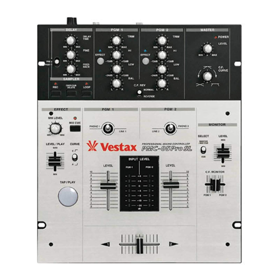
Page 6: Top Panel Section
ページ 6 FUNCTIONS TOP PANEL SECTION TRIM (PGM1/PGM2) This pot adjusts the input level of each PGM channel. For optional acoustic quality, set the INPUT FADER to a position of 7 or 8 then; adjust the TRIM so that a sufficient signal is fed through the channel without distortion. - Page 7 ページ 7 CROSSFADER REVERSE SWITCH This switch reverses the action of the crossfader by switching PGM1 and 2. PGM EFFECT (program effect) SWITCH It is the switch which sends the signal of each PGM channel to built-in sampler / delay. If it is pushed, a signal will be sent to sampler / delay section, and PGM EFFECT indicator will light up.
- Page 8 ページ 8 SAMPLER/DELAY SECTION SAMPLER/DELAY SELECT SWITCH This switch selects the effecter function to either sampler or delay. Moreover, in the sampler side, either Pre I.F. (before a inputfader) or Post C.F. (after a crossfader) can be chosen which signal is effected with the same switch.
-
Page 9: Front Panel Section
ページ 9 MIX VOLUME It is the volume which adjusts the master output level of SAMPLER / DELAY. When you want to monitor the signal outputted from SAMPLER / DELAY by headphone, please set this volume minimum. E FFECT CUE SWITCH It is the switch for monitor sound of SAMPLER / DELAY by headphone. -
Page 10: Rear Panel Section
SERIAL NO. MADE IN CHINA UNDER LICENCE OF VESTAX TOKYO, JAPAN INPUT - PGM 1 LINE 1 FOOT SW PHONO 1... - Page 11 ページ 11 HOW TO USE THE SAMPLER/DELAY Delay Please check before operation that sound has come out from a MIXER or the connected speaker. 1.Set it as DELAY mode SAMPLER/DELAY SELECT switch is set to a "DELAY" side. 2. Set up delay time Strike TAP switch several times, listening to music source if you want to set delay by the speaker or headphone.
- Page 12 ページ 12 SAMPLER NORMAL RECORDING 1. Set it as SAMPLER mode. SAMPLER/DELAY SELECT switch is set to a "PRE-I.F" or"PRE-C.F"side. You can record the signal passed before inputfader on PRE-I.F,and the signal passed before crossfader on PRE C.F. 2. Select the channel to record Please push PGM EFFECT switch of the channel (PGM-1 or 2) you want to record.
- Page 13 ページ 13 OVER DUBBING 1.Turn on loop playback mode Push LOOP switch and set to loop playback mode. (Please check that the LOOP indicator is on at this time.) 2. Start loop playback LEVEL/PLAY volume is raised and playback is started. 3.
-
Page 14: How To Change The Fader Unit
ページ 14 HOW TO CHANGE THE FADER UNIT ■How to remove a top panel ①As shown in fig-a, please remove the knob of INPUT LEVEL volume,CROSS FADER volume, MONITOR- LEVEL volume, C.F.MONITOR volume, and LEVEL / PLAY volume.(A total of six pieces) ②As shown in fig-a, please use a plus screwdriver (size: No.1), and remove the screw of four points which is fixing the top panel. - Page 15 ページ 15 How to change input select switch ①remove the top panel in the same procedure. ②Remove the two screws which fix the switch panel, fix the switch panel, and remove the switch unit from position in mixer.(See fig-e) How to change the direction of the switch ①remove the top panel in the same procedure.
-
Page 16: Specification
ページ 16 CONNECTION PHONO1 SPECIFICATION INPUT MIC IN: (Φ6.3 PHONE / UNBLANCED dBv) PHONO IN:PGM-1∼2 (RCA PIN / UNBLANCED dBv) LINE IN:PGM-1∼2 (RCA PIN / UNBLANCED dBv) OUTPUT MASTER OUT EQUALIZER FREQUENCY RESPONS S/N RATIO CROSS TALK POWER SUPPLY etc. POWER WEIGHT SIZE (W×H×D)...
Need help?
Do you have a question about the PMC-05ProSL VCA and is the answer not in the manual?
Questions and answers