Vestax PMC-05ProIII Owner's Manual
Professional mixing controller
Hide thumbs
Also See for PMC-05ProIII:
- Owner's manual (9 pages) ,
- Owner's manual (12 pages) ,
- User manual (12 pages)
Advertisement
Advertisement
Table of Contents

Related Manuals for Vestax PMC-05ProIII


Summary of Contents for Vestax PMC-05ProIII
- Page 1 OWNER'S MANUAL...
-
Page 2: Table Of Contents
CONGRATULATIONS ! Thank you for your purchasing the VESTAX PMC-05ProIII, Professional Mixing Controller. We suggest that you read through this owner's manual thoroughly so that you may enjoy the full use of this product safely and in the knowledge of all its special features and suitable applications. -
Page 3: Important Safeguards
I M P O R T A N T S A F E G U A R D S READ BEFORE OPERATING EQUIPMENT This product was designed and manufactured to meet strict quality and safety standards. There are, however, some installation and operation precautions which you should be particularly aware of. -
Page 4: F E A T U R E S
・New Look. The new PMC-05ProIII has not only undergone a technology upgrade but it also sports a new look with a new set of rotary knobs. These new knobs are built to reduce slippage and improve fast access at all times. -
Page 5: F U N C T I O N
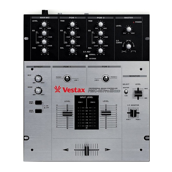
F U N C T I O N S TOP PANEL... - Page 6 qMAIN MIC LEVEL Adjusts the input level of the MAIN MIC input. wMIC EQs Adjusts the HI and LOW frequencies for both the MAIN and SUB MIC input. eMIC PAN Adjusts the panning for both the MAIN and SUB MIC. rTRIM (PGM1/PGM2) Adjusts the input level of each channel.
-
Page 7: Front Panel
@9 P OWER JACK Connect the Vestax DC-15A , AC adaptor. #0 L INE OUT The PMC-05ProIII has two pairs of Line Out jacks sending the same output signal to an external amplification device. Connect your power amplifier or other like amplification device to these jacks. -
Page 8: How To Change The Fader Unit
HOW TO CHANGE THE FADER UNIT q Remove the fader knobs. (See fig-a) w Remove the 4 screws which fix the top panel. (See fig-a) Remove the 2 screws which fix the fader panel, and remove the fader unit from position in mixer. (See fig-b) Carefully remove the multi-cable connector from the fader unit. - Page 9 HOW TO CHANGE INPUT SELECT SWITCH q Remove the top panel in the same procedure. (See fig-a) w Remove the 2 screws which fix the switch panel, fix the switch panel, and remove the switch unit from position in mixer. (See fig-e) HOW TO CHANGE THE DIRECTION INPUT SELECT SWITCH q Remove the top panel in the same procedure.
-
Page 10: Connection
CONNECTION... -
Page 11: Specifications
SPECIFICATION LINE INPUT SECTION PHONO LINE OUTPUT PHONES SECTION SEND FREQUENCY RESPONSE CROSS TALK SN RATIO (WxHxD) DIMENSION WEIGHT NOMINAL INPUT LEVEL -54dBv -10dBv -42dBv -10dBv NOMINAL OUTPUT LEVEL -10dBv 58mW MAX(@47Ω) ‐10dBv 25Hz∼25kHz ≧100dB ≧75dB <0.01% 262 (W) x 106 (H) x 370 (D) 3.5kg IMPEDANCE 3.3kΩ... - Page 12 AUG.2003 PMC-05ProIIIEq Vestax Corporation...
Need help?
Do you have a question about the PMC-05ProIII and is the answer not in the manual?
Questions and answers